Low pressure fuel pump and swirl pot

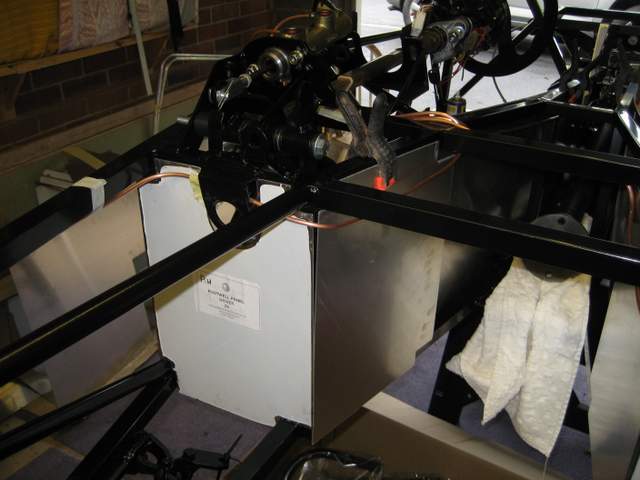
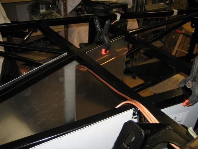
My immediate aim is to finalise the cable and pipe routings through the central tunnel before I start to box this in with side panels.
I have made a reasonable guess at a brake pipe routing so the next pipes are the fuel pipes. To get a fixed datum for the fuel pipes I have decided to start at the back with the low pressure fuel pump and fuel filter. These are mounted on a GBS supplied mounting plate which has pre-drilled holes for the chassis mounting points, the filter bracket and the rubber fuel pump mountings. Positioning the mounting plate and marking the position for the rivnuts on the chassis was straight forward. Drilling the chassis mounting points to 9mm for the rivnuts was a little tricky as it is difficult to get the drill in the right position to drill squarely. But with a little perseverance…..
Mounting the low pressure fuel pump and filter was straight forward although I did choose to add a piece of plastic between the collar and the filter to improve grip, taking care to make sure that the jubilee clip is accessible from above (the eventual boot).
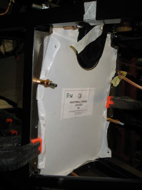
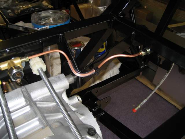
Next I mounted the high pressure fuel pump on the drivers bulk head and riveted the mounting bracket for the  swirl pot onto the chassis. As with the low pressure fuel pump mounting bracket it is difficult to get a good angle for drilling the rivet holes for the swirl pot mounting bracket. Unfortunately GBS supplied small self-tapers in the swirl pot fixing kit instead of 20mm M6 bolts for the rivnuts. As I will be heading up to GBS tomorrow I will pick some up there then and complete the installation.

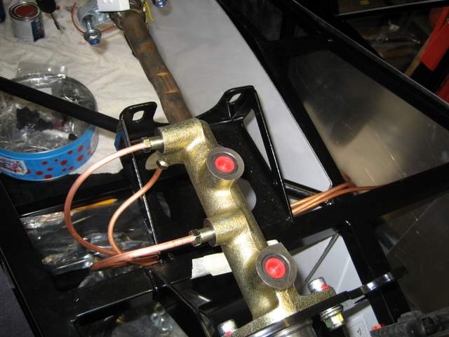
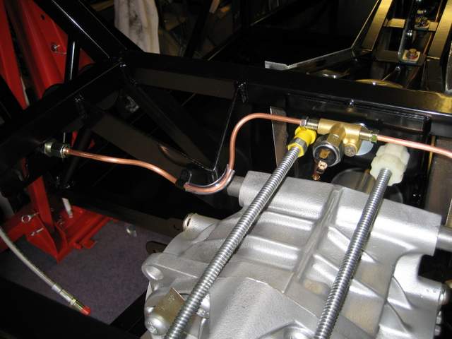
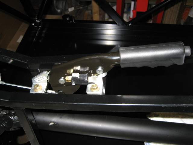
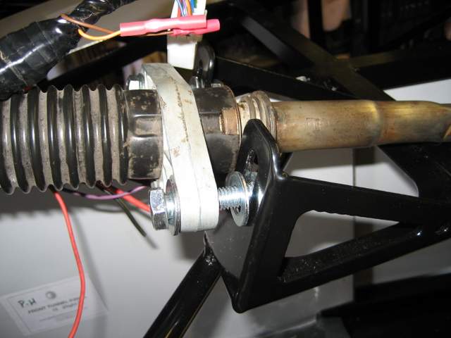
Before I head up to Newark tomorrow I wanted to get a good feel for the routing of the pipes and cables so that I know what to look for. So I threaded the fuel pipes and loom through the central tunnel to get the feel of it. The problem area seems to be above the handbrake Y adaptor and through into the rear compartment. There is not a lot of room and a great risk of the cables/pipes chaffing against the moving parts of the handbrake. I will have a very close look at this at GBS tomorrow.

Foot well and rear seat panels

Just got back from Lanzarote: 30 degrees plus each day, clear blue skies and a nice breeze. Landed at Birmingham: 16 degrees, grey skies and rain. Great to be back.
… but whilst it’s raining there is always work to be done in the garage 🙂


Spent a few hours today, drilling, de-burring and riveting the foot well panels for both drivers and passenger sides as well as the rear panel. 


Cleaned down each panel and frame with white spirit after de-burring, before laying a bead of “black glue” along the chassis to cover each hole. Once riveted, I also added a bead of “black glue” around the inner seam to ensure the panels are a water-tight as can be. Where the panels don’t fit snuggly around the chassis, then I filled the gap with “black glue” also. If this looks ugly when dry I will remove it and try something else. 

I only riveted the flat chassis rails on the back panel and have chosen to simply use the “black glue” for the circular rails. I only riveted the central portion of the left and right edges of the back panel. The reason being that drilling into the corners without a right-angle drill attachment is pretty much impossible, and with all of the other rivets and cement, these extra rivets will not add anything substantial to the stiffness of the rear end.

Footwell Panels

The chassis welding protrudes slightly in some places so a little bit of filing was required to get a good square fit for these panels. 


I marked the chassis position worked out the even spacing of the rivits the drilled and deburred the panels. After clamping in place I drilled the first hole into the chassis and popped a Cleco in. Then went around the rest of the panel.


Both panels are now fully drilled and in situ, but I still need to debur the chassis holes, get the black glue out and then rivet. 

Brake Pipe Routing

Before I fix any of the panels I want to know where the brake lines are going. I have researched the recent blogs and have some photos from a factory build at GBS. Unfortunately the factory build was a left had drive and I had forgotten this. That confused me for a while. 
I decided to star at the master cylinder with the single rear pipe first. Down and under the steering shaft mounting. Over the chassis member and along the driver side tunnel. Under the handbrake mounting and then between the two handbrake cables and under to the splitter.
Next the offside (drivers side) front. Down and under the steering shaft mounting as with the rear. Over the chassis member and the around the front of the drivers footwell panels, leading the pipe straight above the steering shaft and then along the under side of the upper outer chassis member.
Then the nearside front. Down and under the steering shaft mounting as with the rear and the offside. Over the chassis member and straight along the cross member. Then around the front of the passengers footwell panels, leading the pipe straight above the steering shaft and then along the under side of the upper outer chassis member.
This exercise made it obvious that the drivers and passengers footwell panels need to be fixed before much longer as the the routing of the fuel lines is only possible once the swirl pot is in place and the panels need to be fixed before that.

Rear Brake lines

Decided to make a start on the brake pipes. The rear fix as they seemed the least complex. Attached the 4 way splitter with a bolt rather than the rivnut. The hole in the chassis is too big for the rivnut. They connected the brake light switch to the splitter.  

 I started by bending the brake pipes without connecting to the splitter or the flexible braid which I had temporarily fixed to the chassis. This gave me the freedom to bend the pipes in my hands away from the chassis. But, when I came to screw the connectors into the splitter and flexible hose it changed the pipe length once the nuts were tightened. So second attempt was to anchor one end of the pipe (screwed into the splitter) and bend the pipe whilst attached. Much harder, but eventually allowed me to reach the braider connector via a suitable anchor point for a P clip. Courtesy of the local B&Q shop I also added some clear plastic pipe to avoid chaffing as the pipe bent around the chassis at each side.
One thing I couldn’t figure out was which braided hoses went on the front and which on the rear (small or large). Without the suspension and brakes attached it was 50:50. I must remember to ask.

Hand Brake

I still had a little time left, so I looked for another small job that would get me closer to being able to complete the wiring and pipe runs before boxing in with panels.
The handbrake assembly seemed a good bet. This needs to be in place in order to route the fuel and brake lines through the tunnel without risk of snagging against the moving parts of the handbrake.


Not a difficult job at all – just a few minutes to position and bolt the lever down, assemble the link cable and brake cables and attached them all together. I chose to use the lower of the attachment points on the base of the handbrake lever for the link bar. Simply because the cable seemed to snag if I used the upper one.

Master Cylinder

Now the basic clutch/brake pedals are in place, I think its time to fix the master cylinder and push rod for the brakes. I was looking for a short job and this was just perfect – about an hour or so.
Started off reading the Kitspares guidance, and also other blogs. There seems to be a tendency to cut the push rod bold too short which will either leave not enough travel on the brake pedal or not enough in the cylinder itself. The final length of the rod will be determined by where you want the brake pedal to rest (idle) and the throw of the pedal once the brakes are bled. As I can’t determine either at this point I have opted for the safe option – just cut the head off the bolt i.e. push rod at maximum length – for now.
Next job the link pin connecting the pedal to the fork end and push rod. As you can see from the picture the pin is 8mm and the pre-drilled hole in the pedal is not. I don’t think this is a design floor on the part of GBS, rather an efficiency measure. This allows them to make one pedal for both the clutch and the brake.
After drilling the 8mm hole for the pin and filing down the push rod end to fit the master cylinder, it all went together cleanly. I tightened the master cylinder securing bolts just enough to hold in in place and then pressed down on the brake pedal a few times to exercise the push rod inside the cylinder. This moved the position of the master cylinder slightly such that the push rod went in centrally and straight. I then tightened up the master cylinder securing bolts. Job done.


I am not happy with the pedal position at rest – it looks far too high, but I am not going to adjust it until the brakes are bled. There is adjustment on the thread of the push rod or I can simply cut a bit off

Pedals

The fitting of the brake and clutch pedals id covered by one of the few information downloads from the Kitspares download area. The theory is not complicated: locate the plastic bushes into the pedals and the chassis, and add a pivot bar and spacer. In practise, what can seem like a simple job actually tasks a few hours to perform.
I order to locate the plastic bushes in the pedals, you first need to clean the powder coat from the inside of the pedal casings. A barrel sander and some manual emery sanding did the job. Then you need to ease the plastic bushes into the casing with the aid of copper grease (or alternative lubricant) making sure that they go in square. After trying a G-Clamp I eventually opted for a my vice to do this.
For the chassis bushes, I obviously couldn’t use the vice so I used a nut and bold and some penny washers. This was not as easy as the vice but slowly and carefully I eventually eased the two bushes into place.
The real issue with this piece of the build was the steel rod that acts as the pivot for the pedals. This is slightly too big in diameter for easy assembly of the pedals and movement of the pedals once assembled. Unless you have a lathe, it’s pity much an hour or so with emery paper rubbing away a few thousandth of an inch to get a better fit. I have left the fitting quite tight as I expect the joints to get easier over time. 

Looking at the clearance between the pedals and the steering shaft, I think it looks OK. 


Murray has just lost the Wimbledon single s final. 🙁


My youngest daughter had a laptop for her birthday recently, so I re-built her old desktop for use in the garage. I have been using it to follow blogs, but it’s also capable of watching Andy Murray this afternoon whilst I was reducing the pedal bar with emery paper.

Seat Belt Mountings

Whilst the powder coat should keep the rot at bay, it doesn’t help with screw threads -but nothing a 7/16th tap couldn’t deal with. Plenty of WD40 as lubricant. Half turn forward and quarter back. 
All 8 mounting points cleaned up.  Tried the seat belt mounting bolts in the clean threads to make sure.


Differential and Prop shaft final fitting

I managed to pick up a Haynes manual for a Sierra on E-Bay for 1p plus postage.

It defines the torque settings to be as follows:
      Diff side bolts: 60nm plus locktite
      Diff long bolts: 80nm
      Propshaft to diff bolts: 60nm plus locktite
I have also tightened the diff stabilisation bolt to 50nm


So I know where I have been with the torque wrench I have added a spot of red paint on each tightened bolt

Steering Column

In order to be clear about the brake pipe routing, I first need to understand how and where the master cylinder sits. In order to do that I need to understand how the brake pedal interacts with the cylinder and while I am at it, if there are any issues with the steering column as all this happens in a very small area.


I will start with the steering column. A surface dusting of powder rust was easily removed with some emery paper. I thought about a coat a black paint, but the clearance of the nylon bush is too fine, so I will leave it as it is.

 The next job was to change the barrel lock. On the face of it quite a simple job: drill out the lug and out it pops!! But what I have learned is that this seems only to be the case if you have the old keys. There is a circlip at the base of the lock inside the casing. If you can turn the lock such that the circlip aligns nicely with the barrel, then it will just pop out. If you can’t then you will probably have to resort to removing the head of the old barrel and turning the circlip with a screwdriver, as I had to.


Attaching the new steering wheel boss was quite straight forward as was the installation of the lower bush – the spring clip is not shown as I know I will need to remove the steering shaft again at some point to fit the panels


 Whilst I was there I just had to fit the steering wheel and stalks. It is the first time this piece of metal in my garage has started to resemble a car 🙂

The steering rack was next. Not difficult to place or bracket up, but there is something not quite right. With the rack in place and the linkage connected, the steering column is half an inch above the mounting brackets. Next time I go to GBS I will take a look at some factory built cars. I am also not happy with the U clamp on the steering rack. Again I will check with GBS.


Where to start?

There are many, many places I can start. Every box I open contains something I can fix to the chassis, build into a sub-component or clean up ready to fix.
I want to leave the chassis as open as I can whilst the build gets underway. By that I mean I don’t want to fix the side panels too early and thereby become encumbered by them when I don’t need too. I also think that there is a significant risk of me damaging the side panels whilst doing other jobs if I fix them too early.  I must however be cognisant that some of the panels must be fitted in a specific sequence such as the outer side panel before the front suspension, or they simply won’t go on.
So, my short term goal is to get the cable and pipe routings around the vehicle clearly understood before I start permanently fixing panels. 
I will start with the brake pipes….

Organising

Managed to get it all into the garage last night before taking the van back and between heavy showers. Getting the engine off the van and across a flower bed was something to be seen, noy probably not for this blog.


This is what it looked like this morning…..


Time for a very large coffee and some planning. Where to put all this stuff and still have room to build?


Spent the next few hours putting the stuff not needed for a while in the shed and re-visiting the contents of the many boxes. Arranged into some logical order and labelled the boxes with contents to make life a little easier – a bit OCD but satisfying to know where things are.


With some space to work I decidied to start the first build task – the diff. Richard@GBS told me to get the bottom long bolt in first, followed by the front two and then the top long bolt. Great advice, but the spacers were very slightly too large. Maybe the powder coat, maybe a bit of flex in the chassis. Nothing a few strokes of the file couldn’t correct. A fiddly job for one person, but with the weight of the diff taken by the engine hoist it was manageable.


Still a couple of things to do before the diff is complete:

  1. torque up the bolts once I find the torque settings
  2. add a differential rear stabiliser bolt & spacer as it was not supplied (needs a 40mm M8 and spacer)


Pick up day

The day finally arrived. Picked up the van just after they opened at 8:30 and headed toward Newark. Richard@GBS greeted me on arrival with a cup of coffee – always a good start. 


Refreshed I pulled to van towards the roller shutter and we started checking off and loading the van.
Slowly the van filled: box by box and package by package, with Richard@GBS providing a commentary of the build instructions and potential snags and solutions as we went.

The checking process was thorough with each item on the bill of materials being ticked off one at a time. There are a huge number of parts for a complete kit so this took over 3 hours. Disappointingly GBS did have some bits missing:

  • Tyres – they had been “borrowed” for the track day
  • Brake reservoir and cap – having supply issues
  • Catalyst – although Richard@GBS  explained that he is developing a new exhaust with built in Cat which can be re-packed (I will probably swap for this when it’s ready)
  • Steering column surround
  • Anti freeze

Richard@GBS also mentioned that he is working on a new idle sensor to link into the Emerald ECU. I must remember to ask him about this again nearer the time.
Last to go in (not in the photo) was the GRP, followed by the engine right at the back for easy unloading, and finally the gearbox.
I made the mistake of not fully securing the gearbox before I set off. Whilst driving along the A38 a dog was loose running along the verge. A firm touch of the brake and a thud from the back of the van. I stopped in a near by layby to find the gearbox had rolled forward into the GRP nosecone !! 


I hope scratches can be easily polished out 🙁