… and off she went back to GBS for final checks, some set-up that I can’t do i.e. suspension and engine mapping, and the VOSA test. Fingers crossed.

Automotive Projects Blog

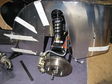
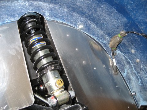
Before putting the car finally back together, the IVA trim has to be added to the edges of any exposed panels especially around the front suspension. This is a frustrating and tricky job when the car is built. Had I known it would have put the trim on before the suspension. Another note for the GBS installation notes.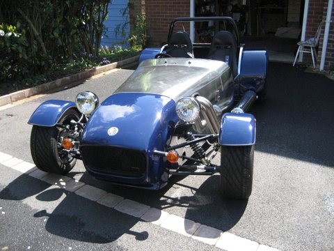
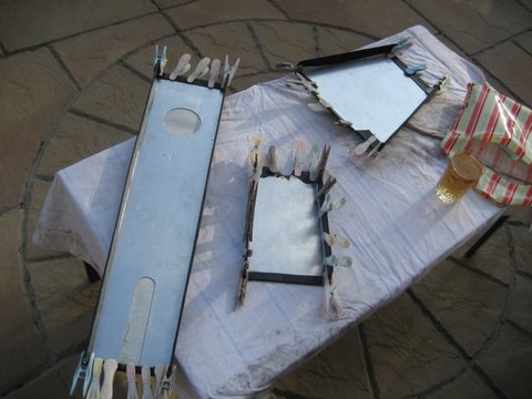
If you have been reading my blogs then you will know my philosophy regarding the final finish for the aluminium panels. So the next and final panel to polish is the bonnet.
And here it is all put together……..

 Seems like I am on the home straight now. GBS have sent off the paper work to VOSA. I have the local garage arranged to move the car to Newark on Friday. Just need to finish off what I can before then. There will be a small list of things I will need to ask GBS to do for me, for example the front wheel/steering geometry, and also anything I simply don’t get done by Friday. I would prefer to continue with the Friday timeline than delay if I am not quite ready.
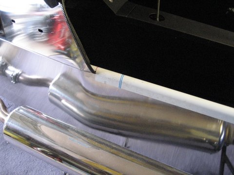 Before I can complete the centre console the carpet needs to go in. I opted for the laser cut carpets from GBS. After sorting out where all of the bits went the installation was very straightforward. I don’t think I had to trim anywhere. Wow is that glue good. Even with the garage door wide open my head was swimming and then aching with the fumes. The carpets transform the look of the interior of the car. All of assudden it starts to look finished.
 My thoughts on the centre console were to use the minimum of fixings to keep the cabin looking simple and tidy. Two for the elbow section between the hand brake and rear panel. Four for the centre section and four for the auxiliary panel. It was then I found that I needed to remove the dash to install the auxiliary panel. But only after breaking the horn switch in the process – damn. Next day delivery from Amazon- I will fix it tomorrow. With the dash out it is much easier to find the right position for the auxiliary panel and drill the holes for the rivnuts. In order to make the centre console fit properly I did need to reduce the centre panels length slightly. Not that easy as the vinyl had already been glued down. I also had to widen the gap for the handbrake lever to make space for the handbrake switch to fit through. The final job was to stick the gaiters for the handbrake and gear stick to the underside.
 Next up is the chrome trim for the door openings and floor. Oddly these weren’t cut to the correct lengths and required some adjustment before I could drill the 3.2mm holes for the stainless steel rivets. I am not sure about IVA for the side pieces. I haven’t put any trim around them as they fit so snugly against the side panels. Fingers crossed.
Finally, and to complete the interior, the seats and seat belts. I had already cleaned the threads for the seat belt mounting points and drilled the floor pan for the seat runners, so both were fairly quick jobs.
Looks great !!!
 Having waited for the tadpole trim to adhere to the wings, they now need to be fixed to the panels. Whilst the panels are pre drilled, once the inner panels are fixed into place, there is no way of poking a pen through the hole to mark it’s position.
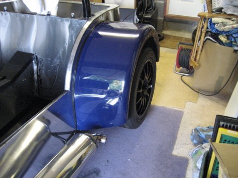
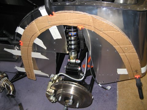 So it’s back to my trusted templating method using the now empty boxes from GBS. Firstly I cut out a template for the rear wing and then fixed it into position on the car. I used masking tape over the fixing points and drew straight lines at various angles running through the centre of each hole that extended beyond the width of the template. With the template back in place I then re-drew the lines over the template to reveal the fixing points. Moving the template back to the wing I then drilled the fixing holes to 7mm to allow a little play before mounting on the car.
 The IVA rules stipulate that the rear lights have to be verticle even though the rear wings aren’t. The standard GBS light units have the appropriate rubber mounts that allow this, so mounting them is simply a matter of finding the point where they are vertical and drilling the fixing holes.
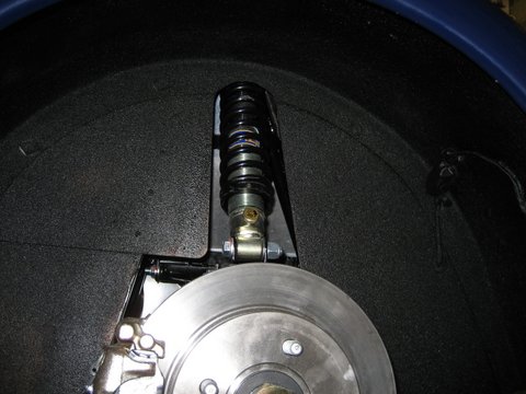
 Under the rear wheel arch is probably one of the harshest environments on the vehicle when driving, especially in the wet. I am not happy to let the simple white plastic electrical connector take the brunt of this environment without some form of protection. Looking around my garage I found an old mountain bike inner tube — perfect!! A short length with a tie-wrap either end should keep the elements at bay.The final step was a coat of spray underseal to provide some extra protection.
 Now onto the front wings. They don’t really fit on the cycle wings at all, rather just rest there. So after tacking into position and leaving to set over night I glued into position with plasters beading which seems to be the accepted way of fixing them in place.
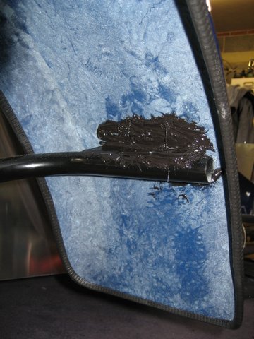
 In preparation for fitting the rear arches, tadpole beading is required around their inside edge. Messy job – I have black glue everywhere!!

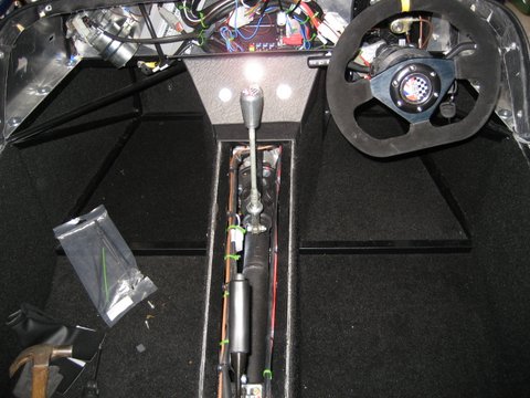
 Time to close up the transmission tunnel. First task today was to offer up the internal panels and drill for the rivets. Then edges of the drivers side panel were given a bead of black glue and the panel riveted into place. I have chosen not to rivet the upper edge as the fixings for the top covers will hold the top in place. Glue should be enough.
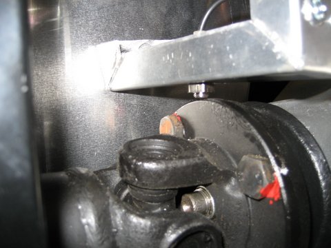
 With the drivers side in place, the next task is to fit the speedo sensor. The sensor needs to sits 1mm-2mm above the bolt heads of the prop shaft. That’s easy with plenty of access, but inside the transmission tunnel its a bit more tricky. I mounted the drivers side bracket, then positioned the sensor before making a template of where the passenger side bracket holes need to be.
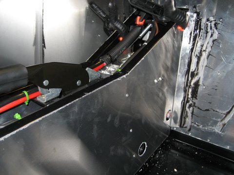
Once I had installed the passenger side panel I then used the template to drive the bracket fixings. The holes needed a little widening but only a mil or so – nothing visible.
 If you have read my blogs from the start you will know that I bought the IACV mounting bracket from RichardL and mounted it on the coil pack bracket.
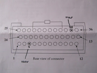
Thanks to RichardL again, I copied his schematic for the wiring of the IACV.
The default settings in the Emerald software do not use IACV, so you need to select it as an option from the Idle Control screen. I first chose manual control from the menu and used the Page Up key to increase the setting to see if the value was working. As it got to 30% the car started to idle cleanly – wonderful.
Next I switched it into mapped and uploaded the settings again. Idle from start is now smooth, ticking over at about 1000rpm. I let the car warm and adjusted the fan control to force it to turn on. No problem either.
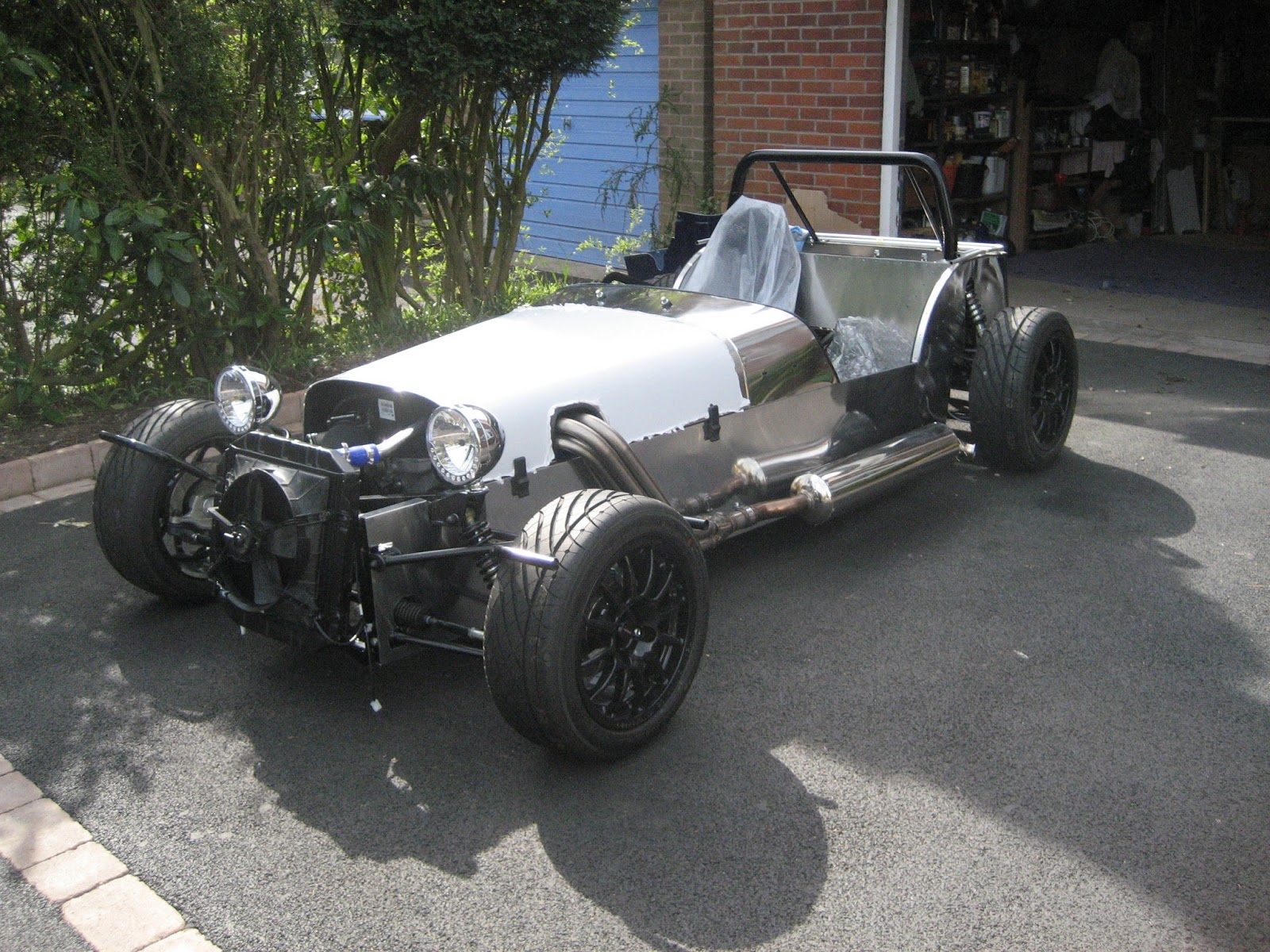
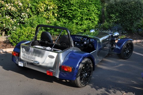
Lovely day so a great excuse to get a couple of photos of the car so far….

Another super day, and to finish off I drove the car back into the garage!! First movement under its own power

After the thrill of starting the engine for the first time, it’s back to the more mundane jobs.
First the auxiliary switch plate with the start button now installed and working.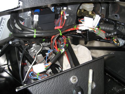
Then a tidy up of the spaghetti behind the dash
Then the glueing of the vinyl to the other panels.
Great finish to a milestone day – sitting in the garden on a sunny evening with a glass of Scotch 🙂


 Running the engine, even for a short time, without a silencer is a VERY noisy experience in the confirmed space of my garage. So the next job has to be the silencer. So that the mounting bracket doesn’t interfere with the rear wheel arch, the manifold needs to be shortened by about 5cm. My dremel made short work of it without needing to remove the manifold. I then pushed the silencer onto the manifold and used its position to guide the position of the bracket. Three 8mm holes later and the bracket was in place.
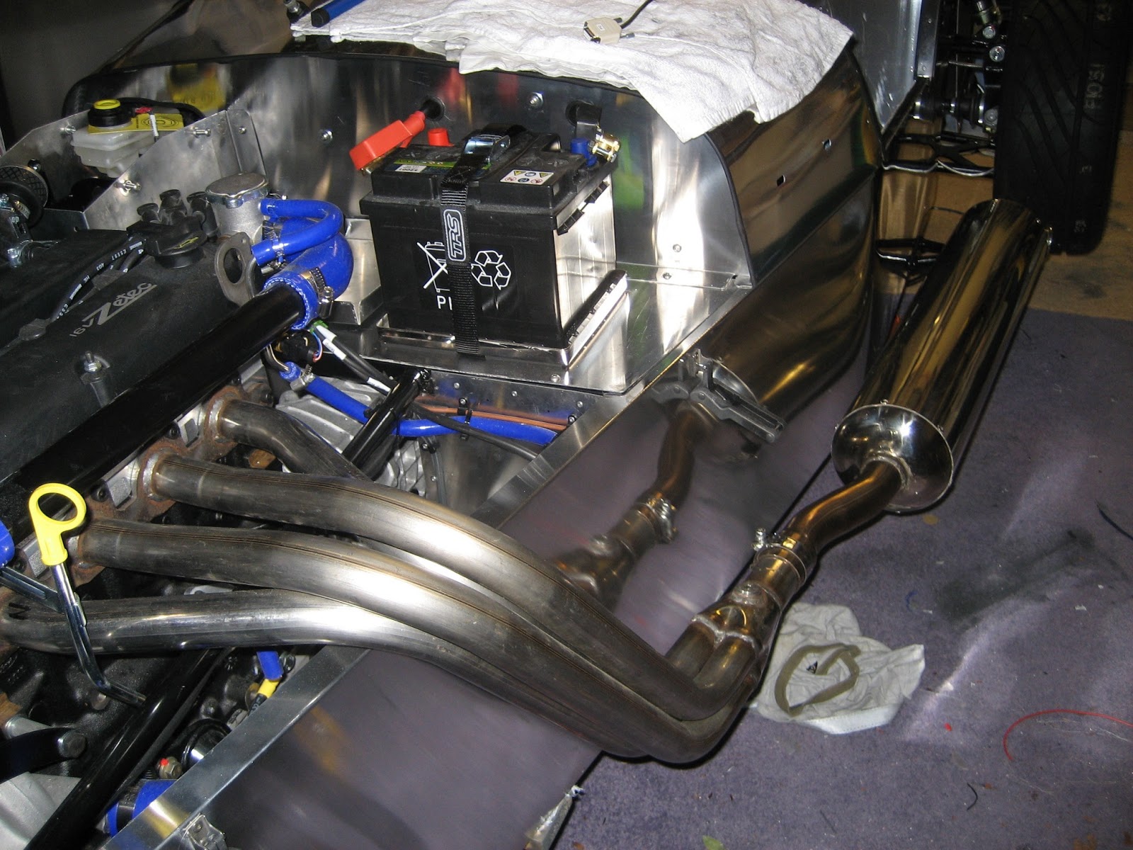
It looks good and thankfully is nowhere near as load
There were a number of small jobs that needed doing first. Attaching the fuse box and ECU to the firewall; routing the battery cables through the firewall; and adding a good earthing point.
Once they were complete there was no excuse as to why I couldn’t turn the engine over.
I have an old laptop with a serial port so I plugged it in and turned on the ignition. GBS had emailed me the power map so I opened that and set up the Throttle Position Sensor. I decided not to use the IACV just yet to keep things simple. I turned the key and the engine turned over but didn’t fire – bugger. There are only 2 key components that an engine needs: petrol and a spark. Assuming one or both of these were missing I set about trying to analyse what was wrong. I started by disconnecting the HP fuel rail and running the fuel pumps – nothing. I was getting somewhere – no fuel. So I checked back along the fuel route back toward the tank to find the blockage / air lock. I found the problem in the connection between the red nylon pipe and fuel hose. I had missed the brass insert when tightening the jubilee clip and crushed it. Having left some play in the piping I cut the pinched pipe off the end and re-connected. This time fuel spurted from the HP fuel rail when I ran the pumps. So I put it all back together and cross my fingers for a second attempt…………..
Awesome……
Seems like the Db rating destroyed the mic on my camera. This ones a little better.

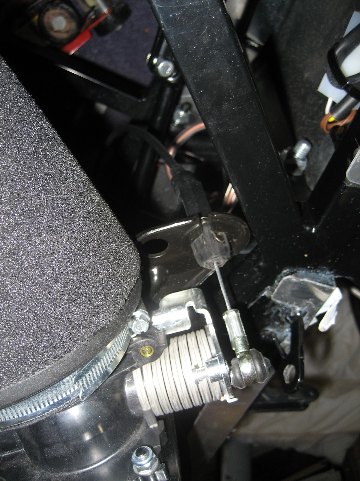 I thought the accelerator cable would go in without much resistance. In fact fitting it to the plenam bracket took less that 10 minutes. But – and there is a but. Once installed there is only about 1cm of travel which hardly opens the throttle. Mmmm. I thought about this for a while and tried repositioning the bracket, but in the end phoned GBS. It turns out that you have to cut 2cm off the plastic bracket and be very careful not to nick the cable itself whilst doing so. As you can see, once this is done you get full travel.
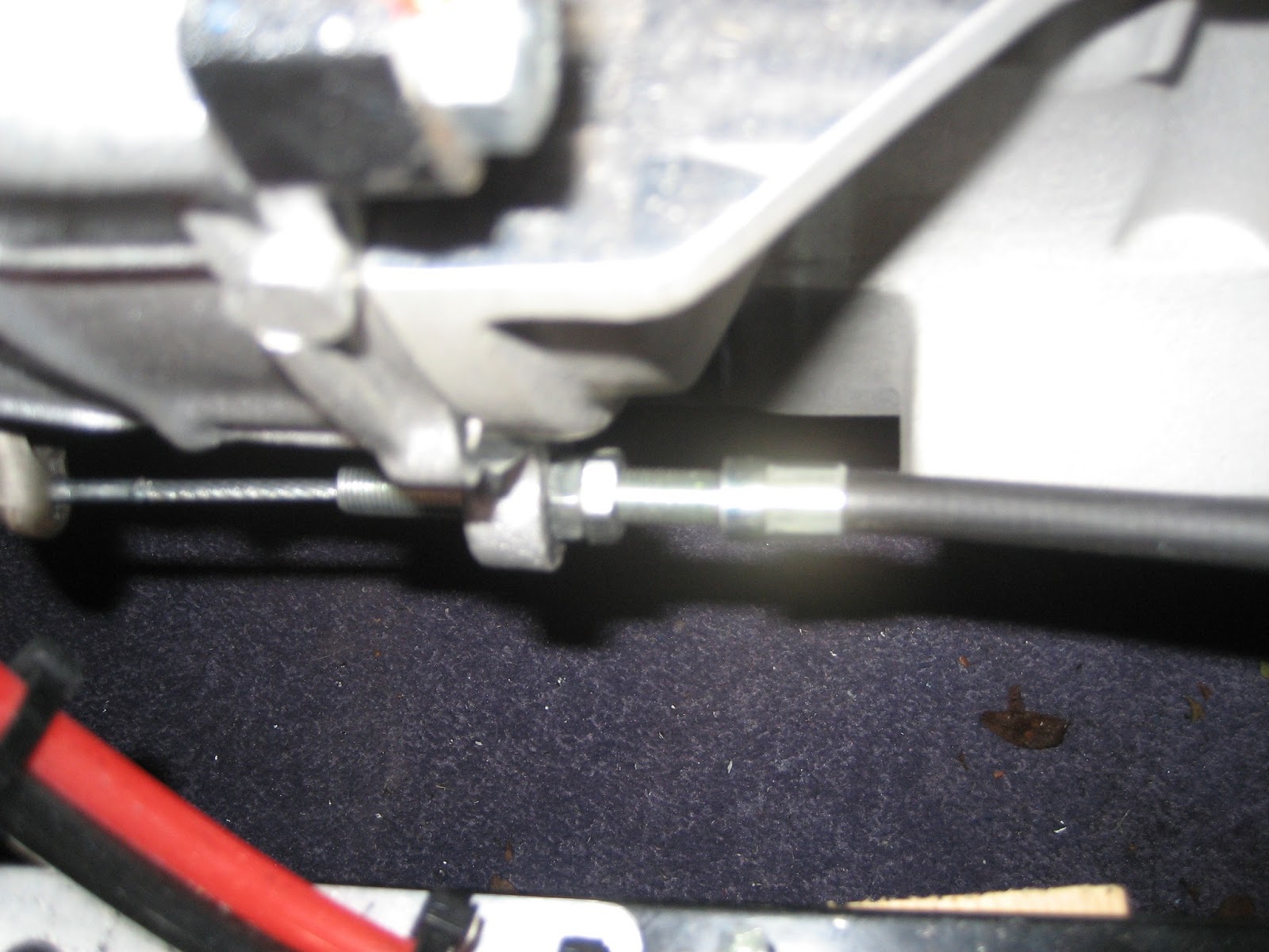 Finally I hadn’t completed the lower end of the clutch cable assembly. I have seen various methods of securing the cable to the bell housing, but I haven’t any nylocs with the correct thread so it will simply have to remain with the 2 lock nuts for now.
 Here is a view of the pedal box with everything now in. I did decide to re-seat the accelerator pedal as I wasn’t happy with the fact that it didn’t swing freely. The pre-drilled hole in the pedal box needed widening slightly and with a little grease applied it felt a lot better.