Rear Suspension & Exhaust

Well the country is pretty much on lock-down now. Covid-19 is wreaking havic in Italy and Spain and I fear we are a week or so behind them. I’ve not been out all week as I am lucky enough to be able to work from home. Whilst it’s a little un-nerving as life as we know it is changed so drastically so quickly, if isolation saves lives and heartache then that is the least I can do.

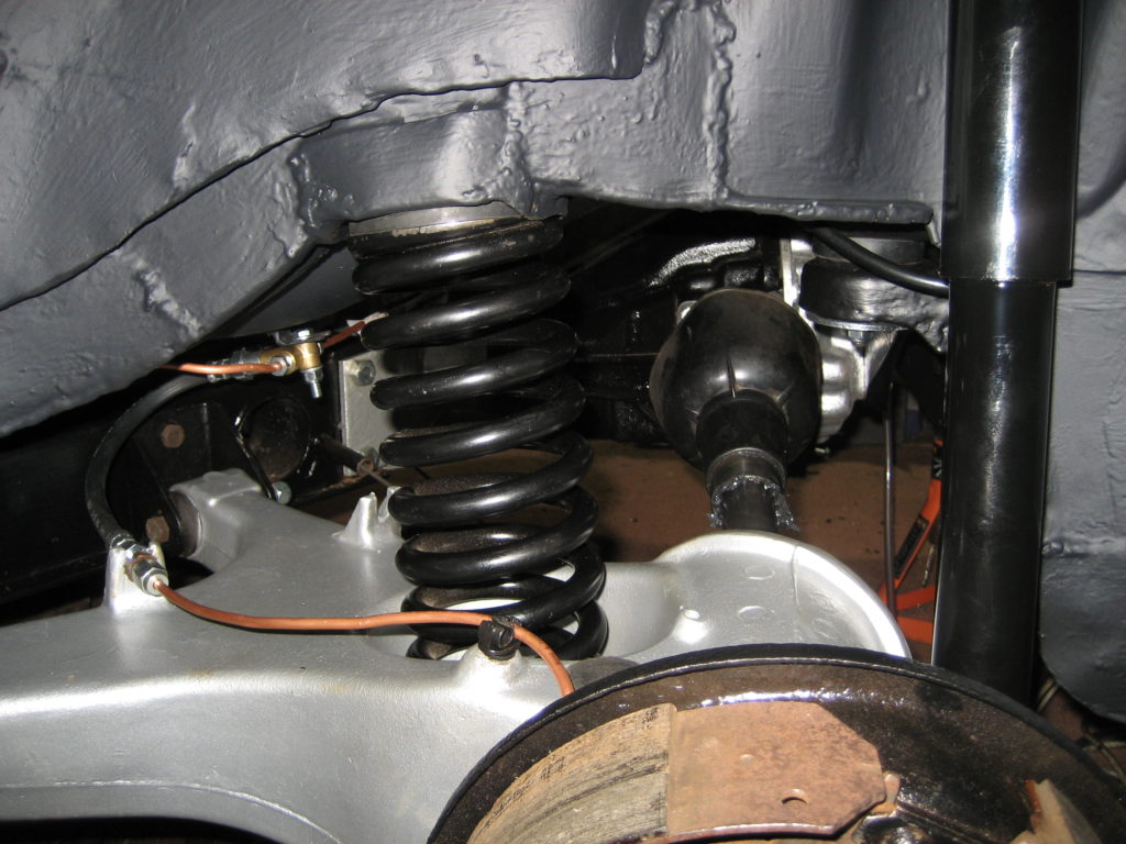
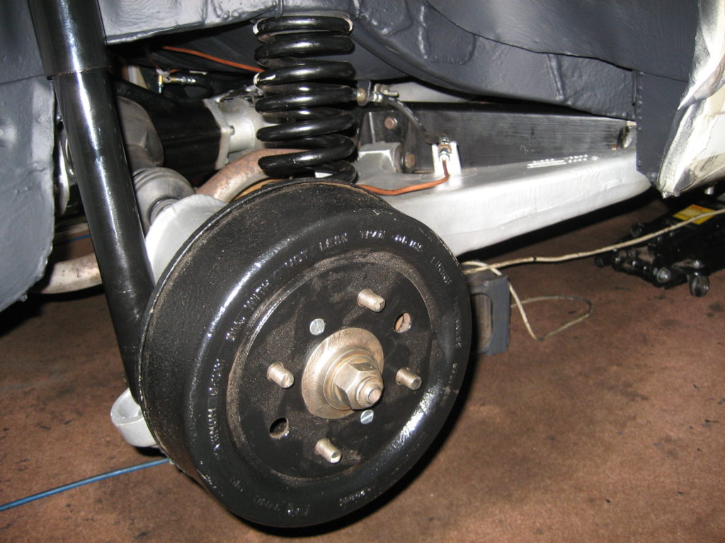
The self isolation has given me far more time than normal to play in the garage this weekend. I have now completed the re-assembly of the rear axle and suspension as well as re-fitting the exhaust.

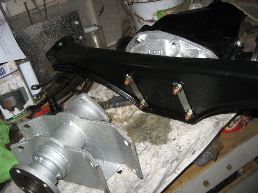
On the drivers side I tried fitting the drive shaft as a single item. Unfortunately the dust cover wouldn’t be forced through the apperature in the trailing arm. So back to plan A, or more accurately before Plan A, because I hadn’t realised how closely paired the inner and outer shaft were. I had heard that they came in pairs but didn’t fully realise the significance. The inner and outer shafts are machined to fit each other precisely. An inner shaft from one pair may not fit an outer from another pair. That’s what happened to me. I must have mixed up the pairs and one pair would not mate up easily. So the passenger side had to come off again.

This time I didn’t attach the inner drive shatf flange to the diff. It was the easier to slot the inner and outer shafts together this way, but more difficult to torque up the flange bolts afterwards.

For the timebeing I have decided to live with the existing exhaust. It hasn’t got that stainless steel snarl I love, but there is nothing wrong with it (although I couldn’t tighten one of the manifold studs). So it’s gone back on for now.

Rear Suspension Assembly

My plan today was to build a new set of gates for my Mom in Wales. Her’s had rotted and blown apart during th recent gales, so I thought I would pop over, take her for a nice Mother’s Day lunch and start building the new gates. Covid 19 has put paid to that as my Mom is 78 and therefore in a vulnerable group. Next on my list was a game of golf as the weather was forecast to be clear and dry. Although the Golf Club was open, it is not essential travel so, in line with the current guidence, I haven’t travelled. So, it was back to the garage – what a pity 🙂

Todays job was to start the re-assembly of the rear suspension. Starting on the passenger side, my aim was to build up the suspension gradually on the vehicle, rather than assemble it off the vehicle and then fit it as one peice. My reasoning was simple. I am doing this by myself with my limited equipment in a domestic garage. A complete rear suspension is just too heavy and cumbersome to move around when you are solo.

Anyway, the first task was to re-couple the trailing arms to the rear sub-frame arms. I had already replaced the bushes so this only involved a little silicone spray and easing the bushes into the steel brackets on the already assembled and painted sub-frame arms.

Then I fitted the trailings arms and sub frame to the quill shaft sub-assembly with the aid of my small trolley jack. Next I connected the inner drive flange to the diff and torqued the 4 bolts up tight. The sequence of re-assembly I chose was because I thought that it would be easier to torque up thes bolts whilst I still had reasonable access. It was, but aligning the inner and outrive shafts was not easy later on.

The main sub-frame bush was connected next through the car body and the ant-vibration strap. Follwed by the outer drive shaft, gaiter and dust cover. As I mentioned above, the precision nature of the inner and outer drive shafts makes it difficult to mate them together whilst also supporting the weight of the hub and brake assembly. I may try assembling the full drive shaft / brake assembly and the trailing arm before I attach to the diff on the driver side – it may be easier.

Finally I installed the new spring, mounting rubbers and shock absorber. I didn’t have time to torque all of the bolts or close the gaiter with tie wraps, but I was very happy with the progress today.

Diff re-assembly

It feels like I’ve turned the corner. All the welding is done: chassis and floor panels. The under-side has 2 coats of Rustbuster epoxy mastic paint and 2 coats of stone chip. Its now time to start putting the rear end back together.

First was a replacement brake pipe between the PDWA and the 3-way connector under the boot floor. Whilst the propshaft was missing, this was quite a straight forward job, especially since I had purchased some new brake pipe / fuel pipe clips and simply replaced the existing ones along the transmission tunnel.

Now to the differential and prop shaft. The photo below is the old diff mounting panel. It was scrap along with the backplate of the diff itself. I found a second hand mounting panel, cleaned it up an painted it. Then swapped the diff for a reconditioned one. As you can see, it looks as good as new now.

As I mentioned in a pevious post, I had already refurbished the quill shaft assembly, so once I had mated the diff to the mounting panel, I attached the quill shaft to the other end. I then torqued up the bolts to the settings in the service manual – see the Torque setting page.

With the aid of my trolley jack, I manouevered the assembly into position under the mounting pins and sandwiched the mounting panel at both ends with new rubber top and bottom mounts and a shiney new lower washer. With the jack taking the weight it was simple to add the 1/2″ nylocs and torque them up. I left the jack taking the weight and re-connected the prop shaft.

I torqued up the 4 connecting bolts to the right settings and managed to damage my left shoulder in the process. The problem was that the torque wrench has a much longer handle than my 1/2″ spanner, and since the prop shaft was able to rotate, my left arm had to mitigate the torgue produced by the longer torque wrench whilst lying under the car. Ouch. That’s enough for today.

Fuel Tank Re-assembly

Now the boot floor has been replaced and the new steel boot floor painted (inside and out), I could now replace the re-furbished fuel tank. Arry the Stag had a recent feature on rusty fuel tanks. Interestingly TR Tony chose a similar method to repair his tank as I had used – see earlier post. During his short video I noticed the routing of his fuel pipe from the fuel pump to the carbs. It was routed through the boot floor under the right-hand corner of the fuel tank.

I tried the replicate this routing but found that the nylon fuel pipe would kink if I tried to force it through 90 degrees as it passed though the grommet in the boot floor. Instead of routing the fuel pipe externally along the rear of the boot, I bought it into the boot through the upper hole in the left hand corner of the boot rear panel, then along the inside of the boot to the pump. There seems much less stress on the nylon pipe this way and therefore less risk of fuel starvation should it kink in future.