Damper struts and final assembly

I refurbished the struts a few posts ago (https://arkauto.co.uk/front-suspension-reassembly-part-3). Putting them back into the torrets in each front wing is a simple process on paper, but as a single pair of hands their weight and size makes this more difficult. I couldn’t hold them in place at the bottom and thread on the 3 nylocs from the top. I could have dissassembled the hubs from the struts, but instead I devised a pin that fitted in the ball joint mounting hole in the vertical link and mounted on my hydraulic jack. I was then able to take the weight of the damper and hub assembly on the jack and slowly ease it up into the turret where I could secure it from the top.

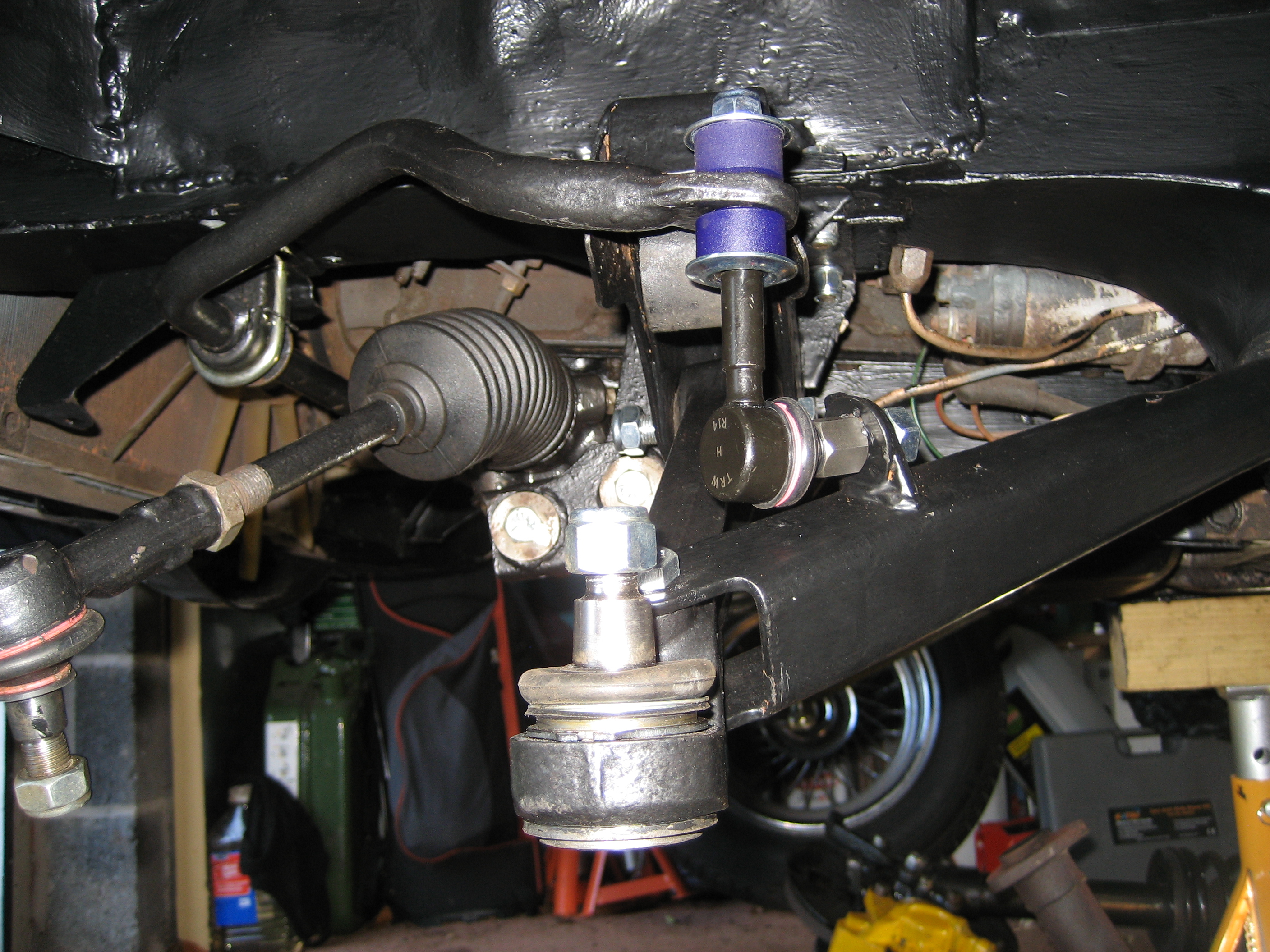
The Leyland Repair manual suggests the use of Plastiseal between the upper surface of the strut top mounting and the underside of the turret. After a little investigation, Plastiseal turns out to be a rubberised bitumen compound, that is widely available nowerdays for repairing roofing. Easy to get hold of and fairly cheap.

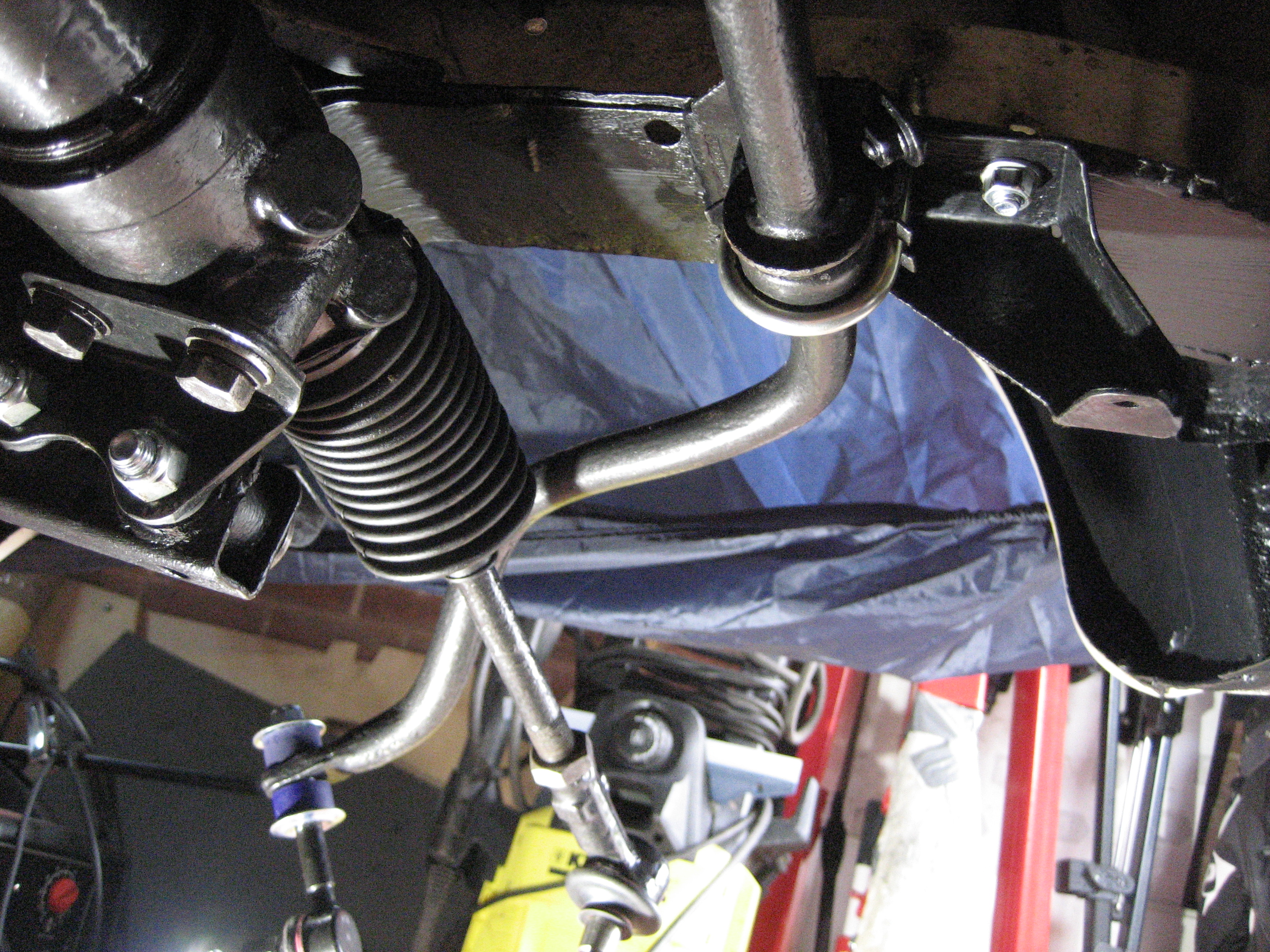
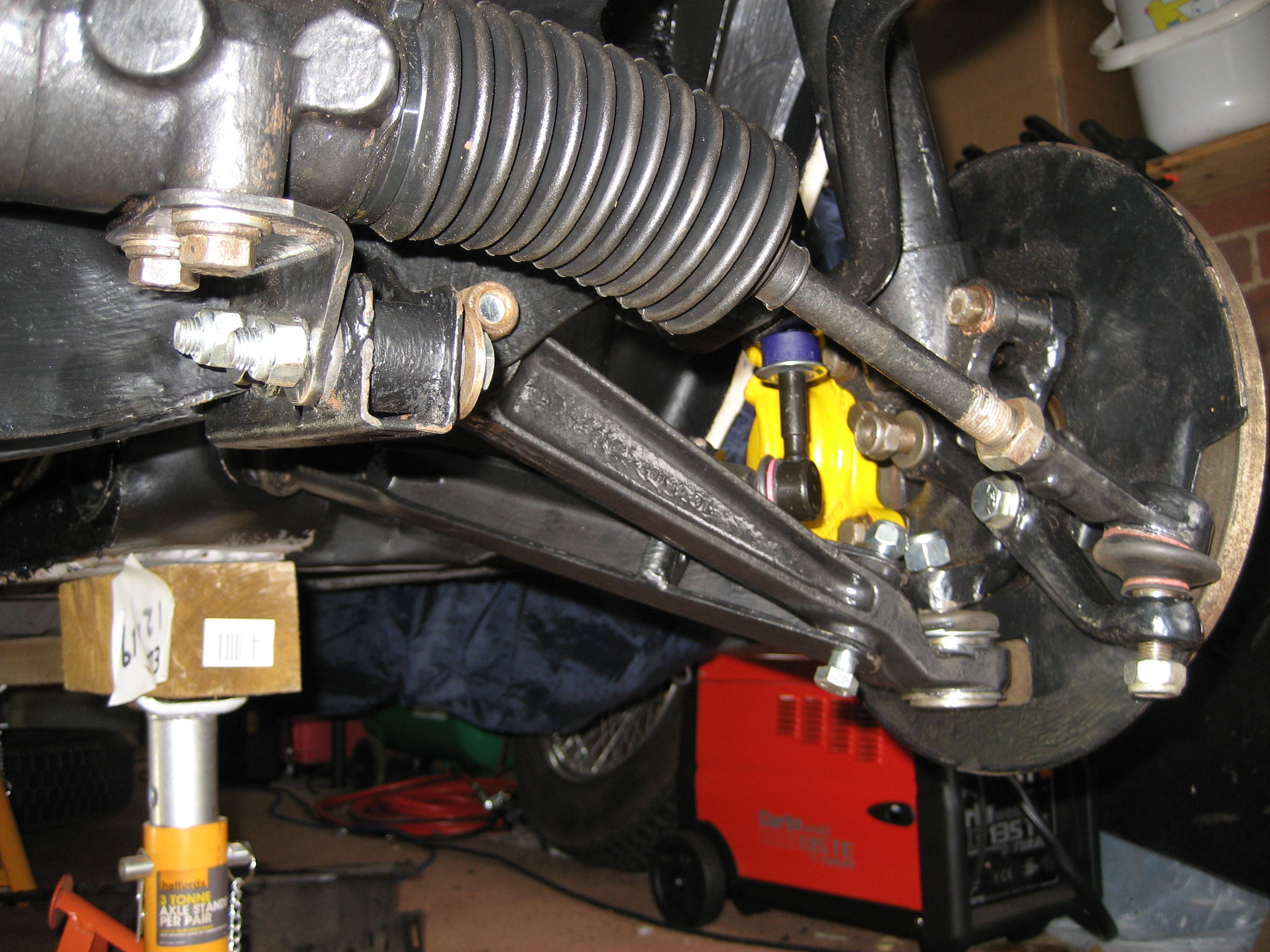
With the damper, strut and hub now hanging within the front wing, the refurbished drag strut, track control arm and anti-roll bar can all be connected with their new bushes, new ball joints and shiny new bolts and fixings. Using the Leyland repair manual and the Haynes bible, I pulled together a list of the torque setting I would need.

They are here for reference – Torque Settings.

Setting the correct torque is all about access. Tightening each element in the right order. This is the order I used, which only left a couple of bolts where I couldn’t get the torque wrench into play:

  1. Anti-roll bar fixing
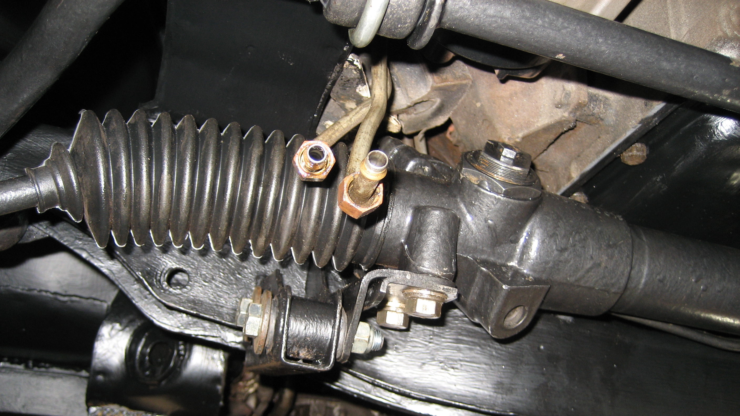
  2. Steering rack mounting bracket to rack
  3. Steering Rack mounting bracket to cross member
  4. Damper to vertical link
  5. Calliper to vertical link
  6. Stub axle to vertical link
  7. Tie rod to vertical link
  8. Ball joint to vertical link
  9. Drag strut to body
  10. Track arm to cross member
  11. Drag strut to track arm
  12. Anti-roll bar to link assembly
  13. Anti-roll bar link assembly to drag strut
  14. Steering rack track rod end ball joint

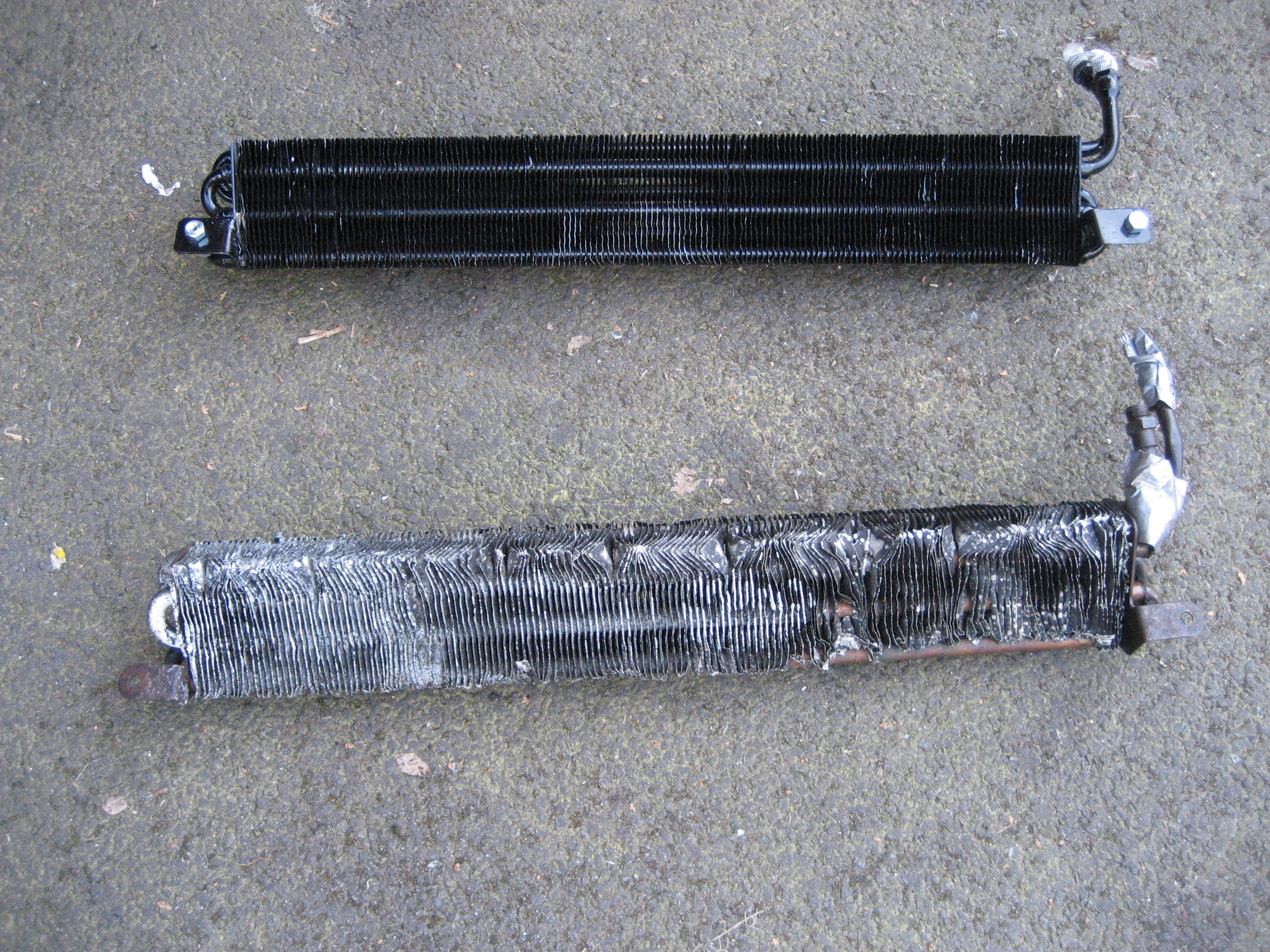
The final job was to connect the replacement ATF cooler. It had to be a replacement. They are so easily damaged that second hand units are in a generally very poor state.

Steering Rack and Anti-Roll Bar

With the sump back on, I replaced the repaired front cross member with some new bolts. The 4 closest to the engine are the shorter (bolt) and the 4 outer ones are the longer (setscrew).

Then the steering rack went back on. I fugured out why the drivers side bracket was a complex 2 plate affair. It allows for the variability in the position and condition of the mounting bushes. Tighten the bolts through the mounting bushes first and then lock down the sterring rack with the 4 bolts through the brackets.

Finally for today was the fitting of the anti-roll bar. I had already cleaned it and repainted it with a couple of coats of hammerite. I had also splashed out on new mountings – bushes, cups and U-clamps. Although I ended up re-using the old cups as the new ones were a little flimsy and didn’t fit well. After completing the trial fitting I realised I had made a mistake. I had forgetten to fit the brackets that hold the Auto Fluid cooler. So off it all had to come so I could get the brackets in place.

Steering Rack Bushes

Time to re-assemble the front cross member. First job is to fit the four new rubber bushes upon which to re-mount the steering rack. Without a press, I use a long bolt, a number of washers and a little lubrication – always helps. Oh and don’t forget to clean the paint from the inside and the lip of the steel tube where the bush is inserted. It makes a hugh difference.

All four went back in without protest.

Replacement Sump

At some point in it’s history, OUA444L had some harsh treatment, or just bad luck. Impossible to tell now apart from the impact damage on the sump. Clearly a heavy collision. A very large dent which bent the sump out of shape. Whilst at the Triumph & MG Spare show at Stoneleigh earlier this year I found a sump that was the correct shape albeit with some surface rust.

With the front suspension and front cross member removed, now was a very good time to tackle the sump replacement. The sump is secured with 21 (yes 21) bolts. 19 screw into the tapped block from the underside, but 2 are bolts dropped in from above with nuts and washer underneath. Puzzling but there must have been a reason.

Once the bolts are undone then a tap with a hammer to break the gasket seal and off it came. The photos show the old sump on the right complete with residual gasket and the engine sludge sitting in the dented base. On the left is the replacement. Cleaned and painted (on the outside) with a nice new gasket ready to be refitted.

Refitting was simply a matter of offering up the replacement unit to the block. Taking care not to dislodge the gasket. Then replacing the 21 bolts. I tightened up the bolts in a manner that would pull the sump in evenly so as not to snagg the gasket. I hope I have tightened each sufficiently – time will tell.

With the sump off i took a few photos of the crank – the block number 1522 can be clearly seen on the left.