Odds and sods…

Went to the Matthew Street Festival in Liverpool yesterday. Such a great atmosphere and so many people just there for the music and the sunshine. Today its raining again. What do you expect for August Bank Holiday. So tried to spend a little time in the garage around some home chores and family business.
First thing was to install the steering rack. Quite straight forward having already shortened and painted the U-bolt. Mounted it mid-to high on the brackets to give a much clearance as possible over the lower front wishbone mountings. Then opened the bag containing the rack extensions. As you can see the thread inside the extension tube is corroded which prevents the extension screwing onto the rack any further than 10mm to 15mm. An M14 x2 tap has been ordered to clean the threads. I am sure GBS would do it for me if I asked but a new tap is £7.50 delivered which is far cheaper than as 120mile round trip to Newark.

I am still undecided as to the final look of the external aluminium. Should I simply leave as is; paint it; wrap it or polish it. I tried the “polish it” option on the top of the boot infill panel. As you can see, you can get quite a good finish with metal polish and an electric drill attachment.
Finally today I placed the internal panels around the chassis to see how it all fitted together. No sure about the boot infill panels below. They seem to have been bend at the wrong angle.

Update 29th Aug 2012: Yes. After an email conversation with Richard@GBS today, the panels need to be bent back to fit flush with the top of the petrol tank. 
Whilst fiddling with these panels, the brake pipe T-junction caught my eye again. When I put some tension on the hand-brake cables after fitting the rear callipers, I noticed that the brake pipe was very close to the hand-brake cable adjuster. I decided tonight that it was too close and moved the mounting mount up a few millimetres. There is very little tolerance for movement here. Behind the mounting place is a chassis bar and you can’t drill into this bar because there will not be sufficient clearance for the brake light sensor to sit under the boot floor.
Front suspension

August Bank Holiday weekend…….Rain, Rain, Rain
Not to worry, plenty to do in the garage…

I was away from home on business last week and had a quite evening where I took the opportunity to reacquaint myself with a few other Zero build blogs. Thanks to RichardL, Aidan and Dave S for sharing their experiences. The question I have yet to decide on is: side panels now or after the engine is in place?
At some point soon I will need to move the car (it’s starting to look and feel like a car now) from the high stands. It will need to sit on it’s wheels, at least for a short time, when this happens. The obvious point is for engine assembly and fit. 
Drilling and securing the engine mountings with the side panels attached is not easy according to the blogs and access is far better with the panels off. I know GBS don’t do it this way, but they have experience of many, many installs and all tools and equipment at hand. I will have one shot and want it to be a simple and predictable as possible given this is the installation of the key component of the car. So my plan is to build up the front suspension without the side panels and not torqued up. Just sufficient for the car to sit on it’s wheels for a while and maybe roll in and out of the garage. There must be a photo opportunity there. I will in due course remove the front suspension and fit the side panels, but only after the engine is in.
So, decision made, it’s on with the building of the front suspension.
I have already populated the wishbones with nylon bushes and crush tubes. I have also already re-tapped the upper wishbone threads for the upper ball joint. So the next step was to bolt the wishbones and Gaz shocks to the chassis. As always, the powder coat needs to be removed from the pre-drilled mounting holes in the wishbones and chassis and any gaps between the chassis brackets and bushes, padded with washers for a “snug” fit.
I have one query regarding the size of the washers supplied with the shock mounting kit. They are only just the same size as the nylon bush against which they press. Maybe these should be a little larger – need to check.
Next I built up the hub by adding the front mudguard support – again I had to remove some of the powder coating to allow this to fit together – don’t forget that these are handed so you need to get them the right way around (look for the notch).
The lower ball joint then bolts onto the lower wishbone. Here I tightened it with normal nuts and used the nyloc as a lock-nut. This will allow the joint to take the weight of the car but not destroy the nyloc before final installation. 

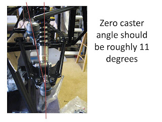
As mentioned a few times across this blog, I may have a passion for engineering, but I am not an automotive engineer and this is my first build. So when I had assembled the upper and lower wishbones and surveyed the result I was a little perplexed. Even after a coffee, more contemplation and searches of several blogs I was still confused.
When I looked at the two ball joints they were not aligned, one above the other. When I looked at the hub the mounting points were aligned one above the other. I took some pictures and sent them up to Richard@GBS. A short phone call later revealed that all was well. For those that have experience in things automotive this is called the Caster angle, and should be roughly 11 degrees on a Zero. Here’s a better description ….

And if you are after further descriptions, I found this informative too…
Caster, tow and camber explained


The front brake calliper then bolts onto the hub. Another query here. As with the rear the supplied bolts protrude through the hub and touch the brake disk. A couple of washers fix this – see photo. Is this OK? – need to check.
Here the final assembled result

And here is the build as it stands. The firewall and scuttle are simply resting there – not fixed

Rear suspension – almost final

I drove up to GBS again yesterday to collect my wheels and tyres, recon gearbox and diff breather pipe. All were awaiting collection – thanks Richard@GBS. The wheels look excellent having now been clothed in Yokahama 195/50 R15 rubber.
Whilst I was there I walked through the torque settings for the front and rear suspension – see Torque Settings.

Today I tightened up the rear, cut down the hub plate to calliper fixing bolts and assembled the callipers. I have found another snag here that I need to talk to GBS about. Once the calliper fixing bolts are tight, the calliper itself touches the brake disk. Same on the other side. I have either assembled something incorrectly or I will need to grind down the hub bracket by 1mm to 2mm to bring the brake disk into the center of the calliper. 
[Postscript – 20th Aug 2012: Guidance from GBS was to remove the powder coat down to bare metal at the ends of each bracket. This done there was still insufficient gap on the off-side so I needed to remove a little more. The disks now spin clear and even within the calliper.]

I spent quite a bit of time scratching my head over this, which has limited my progress this weekend, but I did manage to tap the front upper wishbones. The threads in both were full of powder coating and refused to accept the ball joint. I ordered a M18 1.5 tap from Hong Kong which came on Friday. All is now clean and the ball joints spin down the thread unimpeded. Another oddly satisfying problem resolution.

Even more rear suspension

Both rear corners now assembled, but not yet torqued up. After reading through the Sierra Haynes manual I am not fully clear of what to torque to what. As this is quite important for my own safety I have send a email to Richard@GBS for clarification.

Dash Layout

I had half an hour one evening this week, so I thought I would mock up some dash configurations. I have no intention of finalising the design until the scuttle is in place (many weeks yet), but I wanted my sub-conscious to work on this in the background.
Cut out some dial and switch sized pieces of card and arranged them on the GRP dash.


Found a forum thread will many many examples: locostbuilders

Drive Shaft To Prop Shaft Linkage

Having installed both rear drive shafts, I can understand why they can (almost) independently rotate. This is the main purpose of the differential and allows one wheel to move at a different speed to the other so you can go around corners. What I didn’t expect was that turning the prop shaft did not turn the drive shafts. It rotated freely and seemingly had no effect on the drive shafts. I was expecting some sort of direct linkage.
Is this normal, or do I have a problem with the diff?

I posted this query to the Rhocar forum and in return received this very interesting thread.

Rhocar link. There is a great U-tube link to a video showing how a Diff works – fascinating.

It turned out to be a school boy error in the end. The near side draft shaft was not fully located in the diff.

More rear suspension

Continued building the off-side rear. Nothing torqued up yet but more to familiarise myself with how things go together using my reference photos from GBS as a guide as needed.
The chassis mounting brackets for the GAZ shocks required the holes cleaning before the bolts would fit through. Very tight fit. With the hub bracket in roughly the right position I then pushed the drive shaft into the diff, only to find that I needed to put the calliper bracket on first. The disks need to go on next followed by the calliper itself. The supplied calliper bolts look too long. If tightened I think they would actually touch the pads. I will need to shorten them by 8mm or so when I come to final fit.
Connected up the braided brake lines (long ones) and the hand brake cable so I can see the cable routings.
All looks OK so I will start on the nearside.

Off-side rear suspension

Continued with the off-side rear this afternoon. Another 14 nylon bushes and 7 crush tubes. Again I found this quite satisfying work and hanging the rear suspension feels like real progress

Diff breather question


I have a query regarding the diff breather which I have posted to the Rhocar site.
I notice from other blogs that some diffs have a small tube leading from the diff to which a longer nylon tube can be attached. 

My diff doesn’t seem to have one. Is this a problem?


A very swift answer received from the wealth of knowledge which is the Rhocar forum.
RhoCar Thread


There should be a small pipe attached to the top of this plug that must have been broken in transit. GBS make a replacement.

Pedal box alignment

Just seen a note from RichardL on my previous post regarding pedal box position.
His problem is the alignment of the hole pre-cut in the pedal box for the accelerator pivot and it’s alignment with the hole in the chassis for the other end of the pivot.
Mine looks very similar:
From the top the alignment looks OK. From the front you can see that the hole is 3mm-5mm too high


As none of these panels are fixed yet, below are some shots of the positioning of the pedal box so you can see how I have positioned it against the other chassis components.


Looking from the front I also have a concern about the positioning of the clutch cable aperture in respect to the cable mounting bracket. The pedal box hole looks too far right.

Front off-side suspension

 Although time consuming I found this a quite satisfying activity (strange I know).

  1. Clean powder coat from wishbone tubes
  2. Copper grease the bush
  3. Start the insert with a large M10 bolt and washers
  4. Finish in the vice
  5. Grind crush tube to the total width of the wishbone plus 2 inserted bushes
  6. Copper grease the crush tube and push in with trusty M10


First two wishbones in place – at least temporarily as they will need to be removed to fit the side panels.
Tried to fit the upper ball joint but found sever resistance after only a couple of turns. I suspect it is powder coating in the threads. But I haven’t got a tap of this size so will have to source one.

Steering Column refit

With the hamerite on the steering shaft dry and the information I picked up from GBS during the week, I refitted the steering column. The key mistake I made was fitting the internal nylon bush (that fits on the shaft itself) back to front. It should be fitted from inside the car with the spring clip behind it. This way the rubber gromit and outer nylon bush have no opportunity to pop out.


I have left the final tightening of the nylocs to another day. Once the steering rack is in it’s final position and the connecting rod secured, I am sure the position of the steering column will need adjusting. After reading the long thread on the RHoCar forum about reuse of nylocs, I though this a pragmatic approach.

Final pipe routing

Tried test fitting the firewall and pedal box and encountered a frustrating problem that I know others have also encountered. In an attempt to keep the curve radius of the brake pipes as large as possible on exit from the master cylinder, the brake pipes stick out too far for the pedal box to fit around them. Unfortunately this means re-bending all of the brakes pipes throughout their full extent. Not easy when they are already bent, and not leading to a very neat final job as the pipes now have endless bends in them. This is one of those occasions when an information sheet would be very useful GBS.
Anyway, the pipes are now all re-fitted with additional clear plastic sheathing to prevent chaffing when they get close to chassis and panel corners or indeed each other as with the initial route under the steering shaft bracket.
I decided to route the fuel pipes along the drivers side of the central tunnel and the brake pipe and loom along the passenger side. The tricky bit is the route through into the rear of the car between the chassis and diff and ensuring clearance for the hand-brake cables to move unobstructed.

In the process of drilling my first rivet hole for a P-clip, I discovered that stopping the drill from wondering as I tried the pierce the chassis at an angle is very difficult even with sharp cobalt drill bits. So I made a clamp with a guide hole that I clamped onto the chassis for each hole. Made the process a great deal more predictable and much neater.
Once the nylon fuel pipes were pinned in situ, I connected them to the swirl pot in the front and low pressure pump at the back. I found a problem here with the supplied jubilee clamps. On the small diameter hose these clamps tend to distort and then the screw tends to miss the thread and fail to tighten any further. I think I will source some more and replace them. I really don’t want  fuel leaks and especially ones that will potentially only become visible once the car is almost complete. Replacing them then will be much more difficult.
Finally I connected the hand brake switch terminals and brake switch terminals to the loom, as well as replacing the existing terminals for the low pressure fuel pump for the supplied spades and terminal block.


Trip to GBS

Took a trip to GBS this morning. I dropped my wife at McCarthur Glenn Retail Outlet on the way past, so my time at GBS needed to be brief to avoid serious credit card damage.
There were a number of items missing when I collected the kit:

  • Tyres – they had been “borrowed” for the track day
  • Brake reservoir and cap – having supply issues
  • Catalyst – although Richard@GBS  explained that he is developing a new exhaust with built in Cat which can be re-packed (I will probably swap for this when it’s ready)
  • Steering column surround
  • Anti freeze
The tyres are due in by the end of this week so I took the rims up to have the tyres fitted and balanced once they have arrived. Richard@GBS has finished the development of the upgraded exhaust which includes the cat and packing in a single unit. The packing has been upgraded for better sound absorption and temperature stability and was tested thoroughly at the recent track day. I took my original exhaust back up and will replace with a new system once it’s in production. There are still problems with supply of the brake reservoirs at a reasonable price. Richard@GBS has a cunning plan if this doesn’t rectify itself in the short term: a standalone reservoir mounted on the bulk head with some GBS manufactured interconnect to the existing master cylinder. It will be a few weeks yet before I need this so I will wait and see. It was a similar story with the Steering Column surround although GBS did have a few “tatty” examples. Richard@GBS is working on a custom built design to make the car feel more GBS and less Ford. I decided to wait for the GBS part. The Anti-freeze had arrived, but I forgot to take it – dooh!!. I did pick up a Starter switch though.

The main reason for the trip was to ask some questions and look at examples of part built cars in the work shop. This part of the trip was very successful. I took 80 plus reference photos and came away will answers to all my questions. See “Snags” page updates.

After dragging Moira away from McCarthur Glenn and a leisurely pub lunch I did get round to doing some small jobs on the car. Whilst fetching the kit, I managed to scratch the nose cone when the gearbox moved in the back of the van. I asked Richard@GBS for his advice and he thought that the majority of the damage could be removed with 1200 grade wet & dry, followed by cutting paste and T-Cut. I followed his advice and pretty much removed it, although in a couple of places the scratch was too deep. As you can see, it is now far far better especially with the grill fitted.

 I did manage a couple of other jobs. Completed the placement of the swirl pot and high pressure fuel pump. Gave the steering column a coat of hammerite.