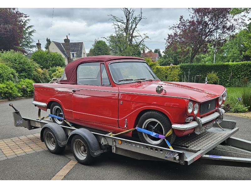
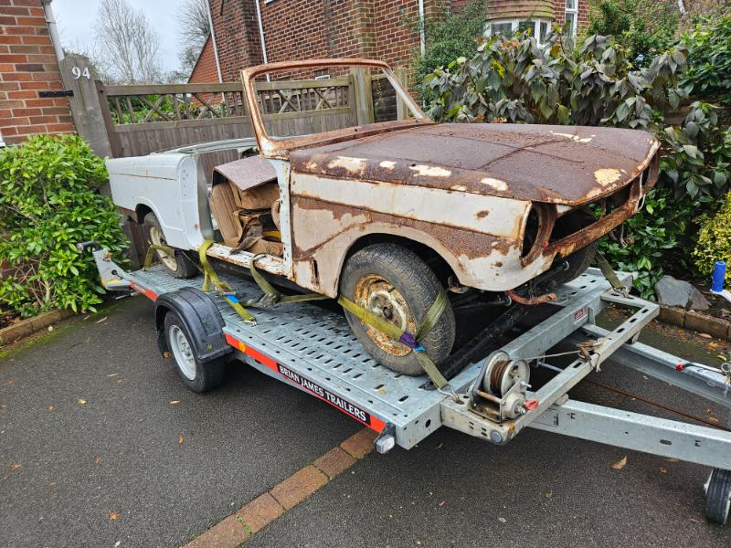
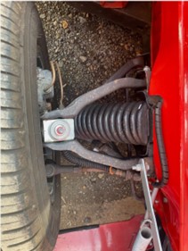
This project is a bit of a bucket list project. My first car was a Triumph Herald (see car history) and since then I have always wanted the bigger engine Vitesse. This is a Mk2 with the rotoflex suspension, overdrive and of course it’s lid free.
Automotive Projects Blog
This project is a bit of a bucket list project. My first car was a Triumph Herald (see car history) and since then I have always wanted the bigger engine Vitesse. This is a Mk2 with the rotoflex suspension, overdrive and of course it’s lid free.
After so fettling of the front outriggers, they now fit around the chassis and allow the front fixings of the bulkhead to bolt into the captured nut on the inside of the front outriggers. However, with these bolts in place the left hand side first and second fixing through the crush tubes on the side rails do not align with the bulkhead brackets. So it’s back to the issue of the brackets in the wrong place.
I could widen the fixing point on the underside of the bracket, but then the captive nut on the fixing plate wouldn’t fit and that would then need fettling. Or I could do it properly and remove the brackets and replace them in the correct position. Only what is the correct position? Are the left hand brackets correct or the right hand ones?
I asked the learned men on the TSSC forum. To my surprise someone else has had the same problem with Chic Doig side rails. Their solution was to create 2 new fixing points (with crush tubes) in the side rail. A lot less work.
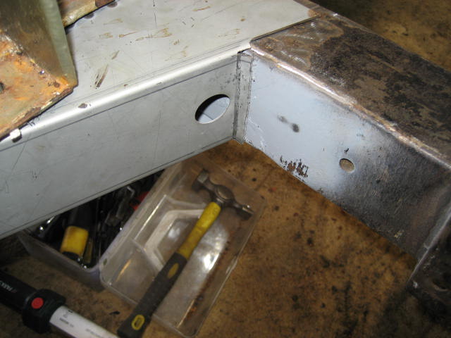
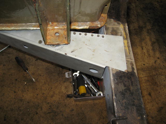
I decided to take their advice. One of the fixings was simply 10mm adrift from where it needed to be, so I drilled a new fixing point in the siderail and welded in a new crush tube. The other fixing point is the one connecting the front outrigger and the siderail. Initially I thought “even easier the crush tube is located on the front outrigger so even less work”. Then my brain kicked in. I couldn’t move the crush tube without also moving the captive nut for the front bulkhead fixing. As this fixing only needed to move a few millimetres I decided to simply drill out the bulkhead bracket. I will also need to adjust the mounting plate but that should be far far easier than replacing the bracket itself.
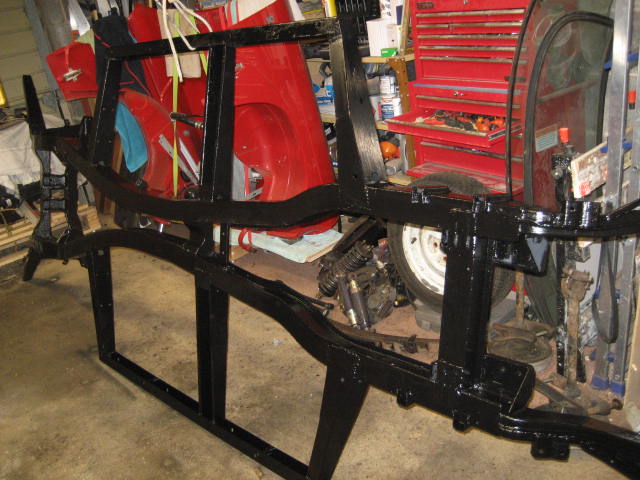
To get ready for welding the chassis components back together I took the opportunity to prime and paint the insides of the new outriggers. I used Rustbuster Epoxy Mastic Rust Proofing Paint as I have used this in the past and quite like it.
To ensure that the new front tub and repaired chassis fit together via the low tolerance fixing points, I bolted the front tub to the chassis before I started welding the new outriggers in place. Simply getting the tub and chassis to align was hard enough with the outriggers able to move. I think welding first, even with a template, would have left me needing to bodge the tub to fit.
With the front outriggers welded in place on the front and upper surfaces, I removed the tub again to finish the welding and start the painting.
It looks brand new again. But this time it has two coats of epoxy rust retardant paint!!
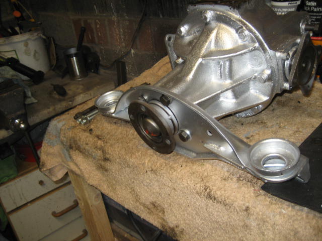
I got a little distracted this week. I finished painting the diff, bought and painted a new top retaining plate along with a couple of new studs and then replaced the bushes in the rear radius arms before painting them too.
Now to start the chassis. First job was to get rid of the oil, dirt and surface rust. I thought of taking it to a sandblaster, but in the end I used a tried and trusted method – wire bush and elbow grease. With a wire brush attached to a hand drill I managed a reasonably thorough albeit dirty job. A couple of passes each side was enough followed by a rub down with degreaser. My final task was to cover the exposed top surfaces with rust converter and then leave for a few days to cure. I used Rustbuster FE-123 after very pleasing results on the earlier Stag restoration.
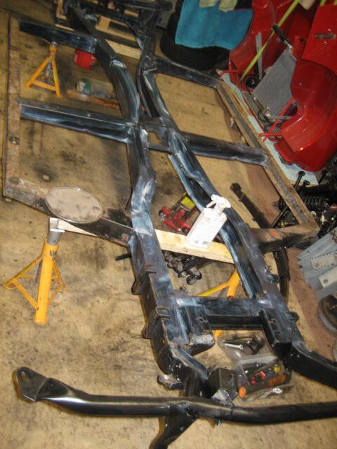
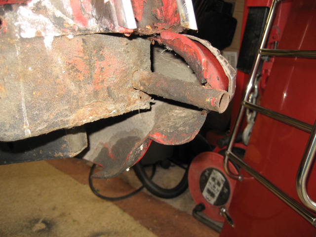
Next was to remove the rusty bits – namely both front outriggers and both side rails. Cutting the sections away from the good chassis was a fairly straight forward task with an angle grinder. What really took the time and patience was the removal of the previous welds in order to get the chassis back to it’s original dimensions. Under the welded ends of the front outriggers I found a couple of rust holes. These I carefully removed and replaced with some fresh steel of the same thickness as the chassis. I am not a professional welder but I thought the end result was robust and reasonably neat. I also needed some slight repairs to the centre outriggers.
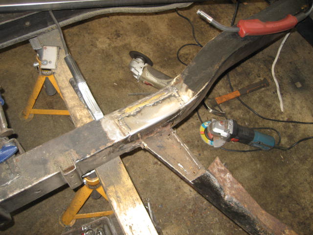
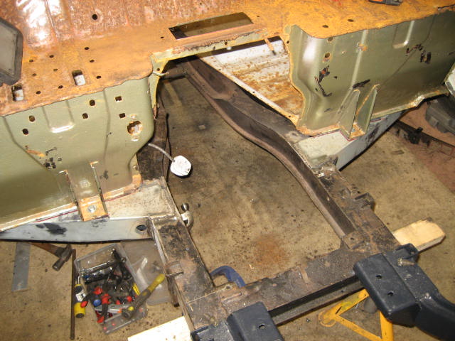
I bought new heavy-duty replacements from Chic Doig in Perth. These slotted into place without much fuss. Before I could secure them in place however, I needed to make sure that they were in the right place for the front tub to drop onto. Unlike the rear tub, the front tub has close clearance fixing points. In effect this means that once the front is bolted to the chassis the rest of the is aligned to it.
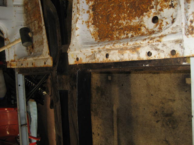
These close clearance fixing points are at the centre of the front outrigger, the first and second holes through the side rails and the 3 fixing holes in the centre outriggers. On the right hand side (drivers side) I managed to get bolts through all of the close clearance fixing holes. This is easy I thought. With these in place I began on the left hand side. The fixing holes along the side rail seemed ok, but the centre front outrigger and the 3 holes in the centre outrigger were not even close. A full centimetre of more a drift of where they needed to be.
After careful inspection I noticed that the front floor to siderail backets are in slightly different places on the left and right sides. Roughly 7cm from the front on one side and 6cm on the other. That doesn’t seem right. Let me try and find some schematics.
Couldn’t find anything that included the dimensions and detailed location of the brackets on the underside of the bulkhead. So I’m just going to have to line things up as best I can.
I have managed to deduce from the car workshop manuals that the chassis crossmember beneath the engine is the datum point for all of the car schematics, so I figure that the bulkhead must be precisely parallel to the chassis cross member. The schematic also defines the chassis side rails as being parallel and therefore equidistant apart along their length. So I have positioned the bulkhead precisely parallel and put some temporary bolts through the first two crush tubes in the chassis siderails and the bulkhead fixing brackets. I can now see the front tub sitting properly on the chassis even though the brackets are not the same distance from the front of the bulkhead.
With the bulkhead in what seems like the correct position, I can see two problems I will need to fix:
2. The left hand middle outrigger has been fitted at an angle. It should be at right angles to the chassis side rails but it is not close. As a result the 3 fixing points no longer align down the centre of the chassis rail. I may need to replace the outrigger.
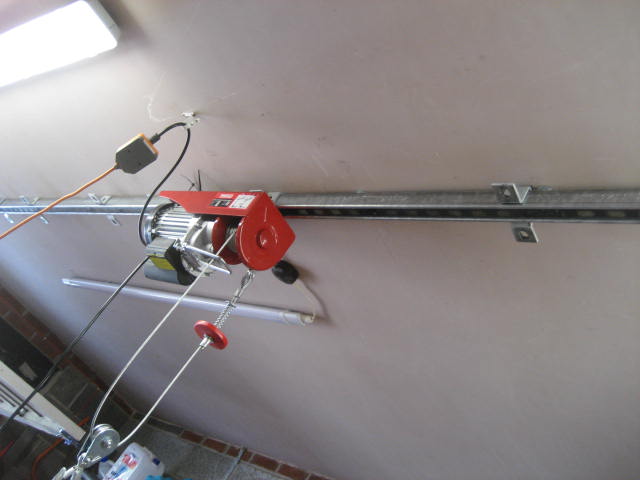
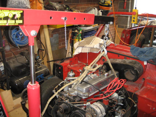
Due to limited space in my single garage, I had left the bonnet attached to the car, but now it has to come off. Easier said that done. It is heavy and bulky to manoeuvre on your own. Just taking the weight to unscrew the spring levers was virtually impossible. I needed something to take the weight whilst I undid everything, and then something to lift it up whilst I pull the chassis from underneath it. The solution I came up with was a ceiling mounted winch.
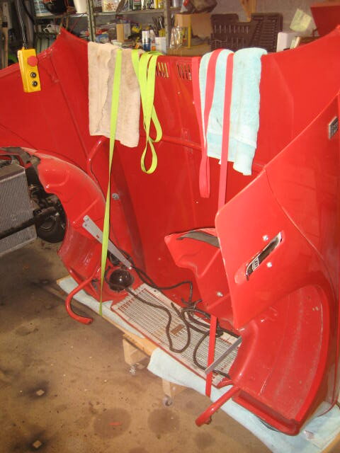
With the winch taking the weight it was fairly straightforward to lift the bonnet off the car and onto a wheeled trolly I made.
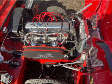
Now I can get full access to the engine bay, the radiator and side cowlings were removed. Followed by the earthing straps and the bolts to the rear and then the front engine mountings. With the prop shaft bolts removed just behind the overdrive, the engine is now free to be removed.
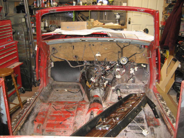
The temperature has finally reached a level I can tolerate in the garage, so it’s time to pick up the restoration once again. There are just a few more components to remove from the shell before I can remove it.
Today I started with removing the wiring loom. The dashboard clocks and lamps have already been disconnected from the loom along with the rear lights, so it was just the loom from the bulkhead forwards that needed disconnecting.
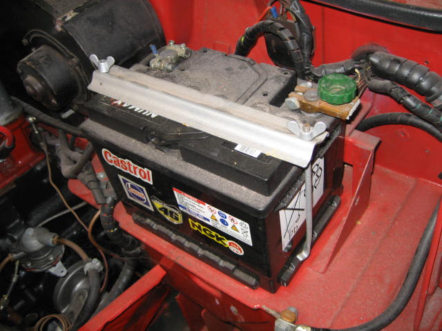
I started with the battery. I thought it odd that the quick disconnect fitting was on the negative terminal, but I don’t suppose it matters from an electronic perspective. Behind the battery there was a small fuse box with 2 wire filament fuses. I made a mental note to replace this with a modern equivalent when I come to rebuilding.
Then came the bonnet wiring. The side lights and main beam units were straight forward since the wiring was original and aligned to the standard wiring diagram colour scheme. The horn wiring had been replaced with all purple at some point. I mad a note of the loom fixing points in a number of photos.
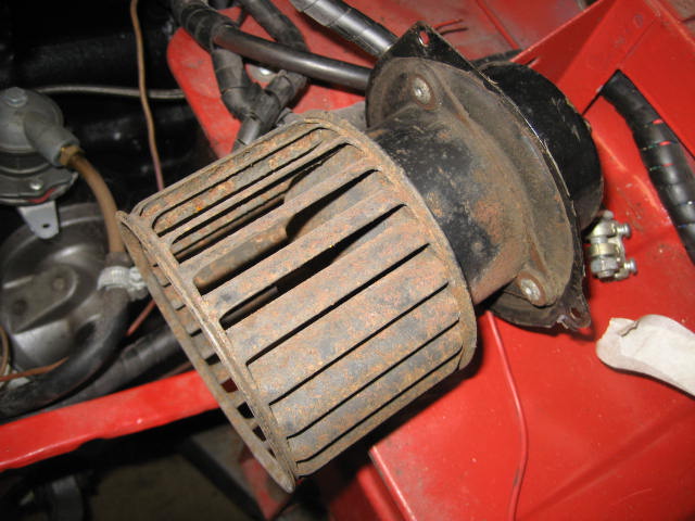
Next was the heater fan which I removed from the cowling and disconnected from the loom. Then the engine ancillaries: oil pressure, alternator, water temp, starter solenoid, overdrive relay and the overdrive wiring itself.
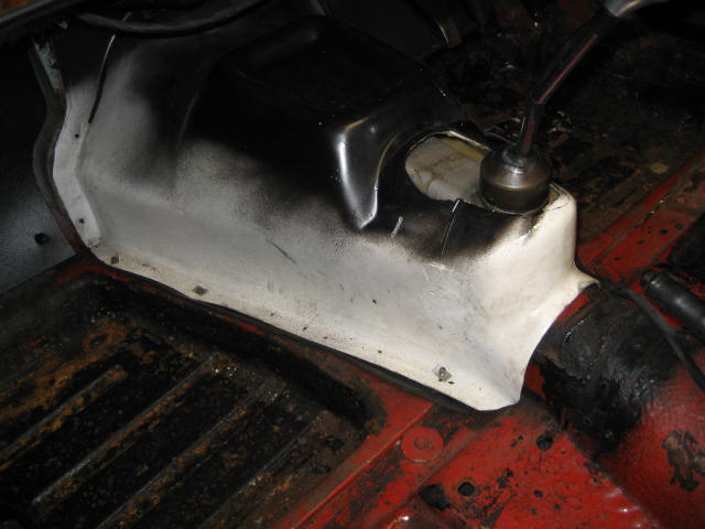
With everything disconnected the final puzzle was how to extract the loom from the car. I decided to remove it from inside the car rather than inside the bonnet. By that I mean I pulled the engine part of the loom through the bulkhead into the car. I needed to widen the hole in the bulk head slightly to allow the alternator connector through, but I couldn’t see an easier method.
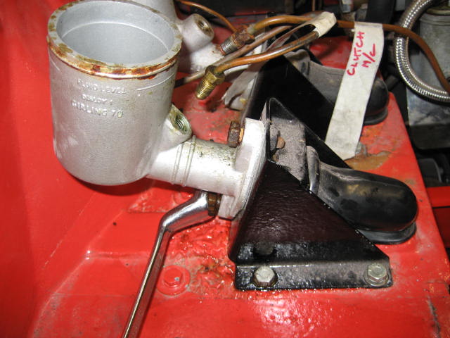
This the loom removed the next to go were the brake and clutch pedals and master cylinders. After draining the cylinders this was simply the removal of the bolts.
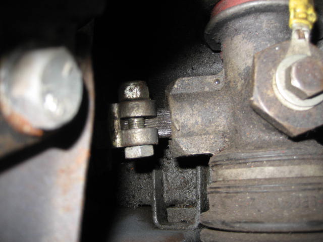
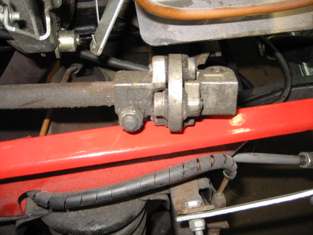
The final steps now. Removal of the steering column and disconnection of the heater matrix. The steering column is detached from the steering rack with a clamp that holds the serrated column, however to remove the complete column into the car I found I also had to remove the knee joint.
To disconnect the heater matrix I simply drained the cooling system and removed the pipes connecting the block to the heater.
So I now have the front and rear tub disconnected from the chassis and the rest of the car.
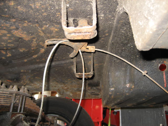
…. Or so I thought. After unsuccessfully trying to lift the rear tub from the chassis, I realised I had not removed the handbrake cable guide. I knew about it, but it sits behind the prop shaft and I thought at that time it would be easier to remove later. I was right – it was.
Today I braved the low temperatures for another few hours of disassembly. The throttle cable and the throttle peddle were first out followed by the footwell backing boards and insulation behind them. Then the speedo cable and RPM cable followed by the heater control cable. As I am dismantling I am taking copious photos and trying to label everything in ziplock bags and then taking of photos of the bags so I know where everything went.
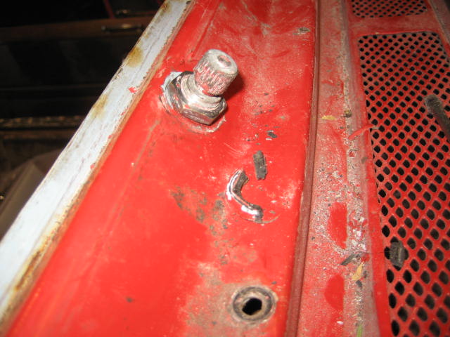
Next was the wiper motor, wiper cable and the trunking that protects it. All was going well until I tried to remove the wiper boxes. I was curious as to why the wiper arm mounting and lock nut had been painted body colour as the lock nut was originally chromed. The reason was that the lock nuts on both sides had ceased onto the wheel box threads and been left in-situ when the tub was repainted, rather than being removed. Both will need replacing along with the rubber gromets they sit on. Rimmers has them listed as Wiper Box – 32 Teeth – 122781 Qty Req-2, vehicles from 1969. I will need to check if mine is the 32 teeth variety by looking at the gear wheel in the wiper motor which should have 160 stamped on it.
At this point I needed to warm up, but there isn’t much more to do before the front tub can be removed. Just the brake and clutch master cylinders, the heater and disconnection of some more of the wiring loom.
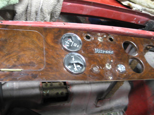
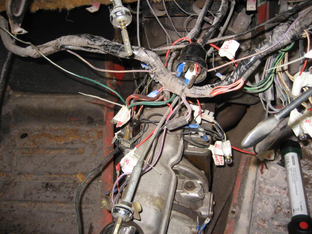
Firstly, the straightforward stuff: windscreen wipers, water jets, steering wheel and the windscreen. With the windscreen removed, then removal of the air vents on top of the dash and the dashboard itself, is a lot easier. Looking at the additional switches added to the standard dash layout, I knew someone had been fiddling, but one peak behind the dash confirmed the extent. I bit of a rats nest. I will need to trace many of the wires to figure out what has been done. I will also definitely need to redo the earthing. There were earth wires strewn everywhere. Some grouped and connected to the back of gauges but not even tightened up. I am sure most of the dash functionality would have been intermittent at best.
After some time on the keyboard and a couple of visits to potential candidates, I found one. Well not just the rear tub. I ended up buying pretty much the whole car. The back story here is that its owner had started the restoration a number of years ago but has since been distracted by other projects and the car has been sitting under tarp at the bottom of this garden ever since. I hope he won’t mind me using his first name here, but Dave has a passion for building small steam tractors from steel, brass, drawings and his lathes. His engineering skill and attention to detail are something I can only admire and wonder at. I fear that when Dave and other engineers of of his generation finally turn their lathes off, we will lose this capability for ever.
The car Dave had started to restore was a 13/60 convertible. The rear tub had been refurbished and fully painted. The front tub was likewise almost finished as was the chassis. The bonnet and ancillaries were yet to be completed. The car was still in pieces, but that was fine as it would save me the job of dismantling it. Not only did this car cost me less than the price of buying new panels, and save me the time of welding them all together, I also bought some of Dave’s engineering skill as I an expecting the welding and structural integrity of the shell to be as precise as components he is making for this steam tractors. And the other major positive was meeting and talking to Dave. Great chap.
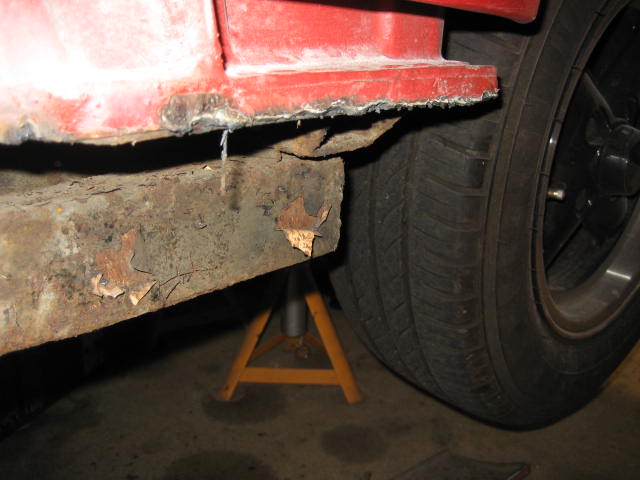
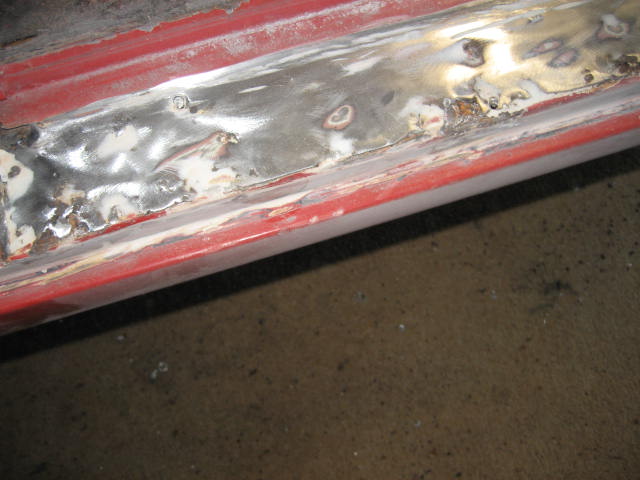
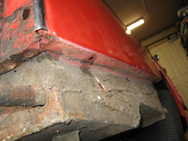
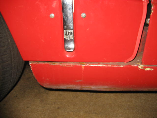
In order to see where and how the sills had been welded to the tubs I got my flappy grinding disc out and removed some paint from the treat plates. Oh dear. Filler and rust. Why to “restorers” do this? It should be a criminal offense compromise the structural integrity of a classic with inappropriate welding where it wasn’t needed and using filler instead of new welded steel where it is needed. Rant over.
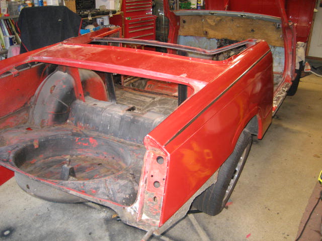
Having cut the sills off the rear tub is finally free to move. I am now at a decision point. The rear tub needs the following work:
All but the brackets can be bought from a number of suppliers and I am sure I could weld it all together given time and patience. The alternative is to source another rear tub and swap it over. Time to hit the keyboard and see what’s on offer.
There is a lot of welding work to do in the boot. The floor, both boot corners and the inner wheel arch. Whilst I understand that major welding jobs are best done with the tub bolted onto the chassis to make sure it will fit back when finished, I also appreciate that some of these jobs could be done with the tub off the vehicle for easier access. Especially the stell preparation, sealing, priming and painting. As I have previously mentioned, moving the rear tub would also allow me to make sure that the issues with the door closure could be fixed with tub repositioning.
Are here the fun starts. Having removed bolts holding the chassis to the rear tub (some needed an angle grinder) the tub remained firmly in place. Then I realised why.
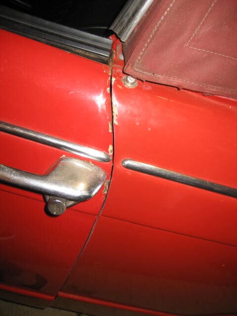
THE SILLS HAVE BEEN WELDED ON!!.
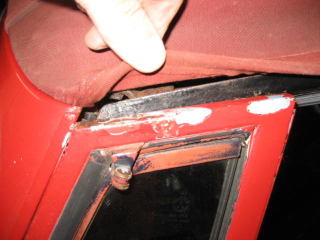
Not just to the rear tub but to the front tub as well, effectively bonding the front and rear tubs together. And to make it even worse, the welding has been done with the front and rear tubs misaligned which is why the doors wouldn’t shut properly.
So the next job is to cut the sills off.
First to be removed were the chrome rear overriders. Two bolts each from inside the boot to captive nuts on brackets welded to the inner overriders. Easier said than done. The long lower bolt on the right hand side was seized and eventually seared after destroying the captive nut encloser. Job for another day.
Then came the rear valance which was riveted to each rear side valance and bolted to the tub with a series of bolts under the boot seal and the boot catch itself. Whilst drilling out the rivets I realised that all of the rear valance panels were fibreglass. I’m not sure they will be going back on.
After the right and left rear valances were removed it allowed access to the boot floor side panels which will both need attention along with their adjacent boot floor sections where the chassis bolts through. As I was working in that area I also undid the chassis bolts on each side. The right side put up a bit of a struggle as a previous owner had already rounded the bolt heads.
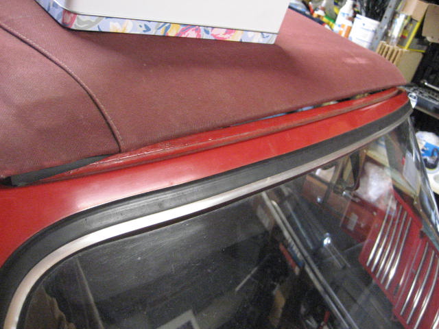
Whomever put this back together the last time did not do a good job. Although the hood is of good quality, it’s fitting was very poor using whatever bolts/screws were available in the workshop and without any effort to maintain the frame itself or its fixings before the new hood was fitted. The frame will need sand blasting, painting and the hood will eventually need replacing – probably black this time.
One question I will need an answer before I start re-assembly is how to position the hood header rail and the quarter lights in both doors. Do the quarter lights sit under the header rail or alongside it? Do the tops of the quarter lights sit flush with the top of the windscreen surround? I need to find a car show and take some photos of good examples.
My initial focus is to slacken the bolts holding the rear tub, and make sure that the door and bonnet gaps will eventually be able to look the part once the car is finished. To do this I started by:
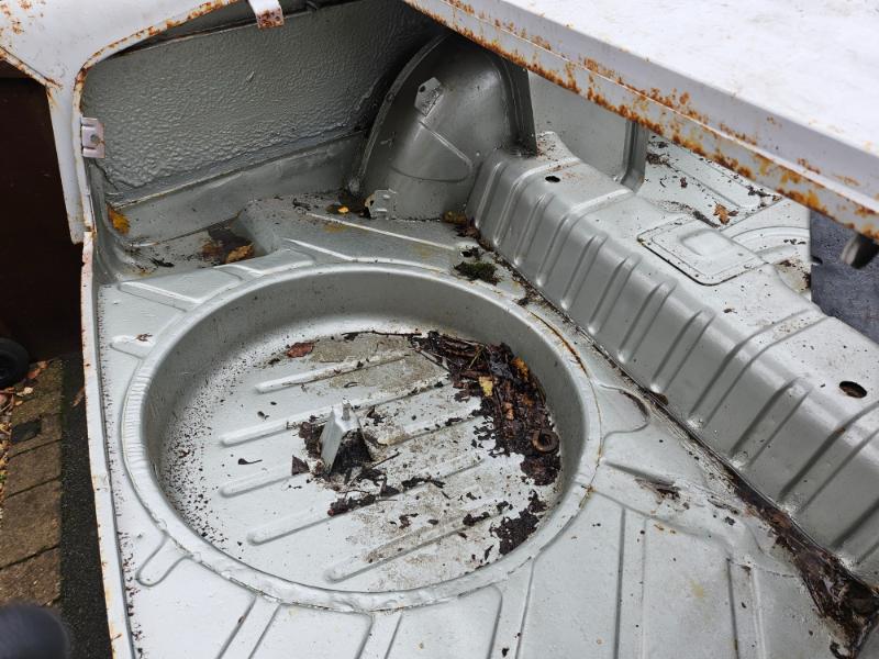
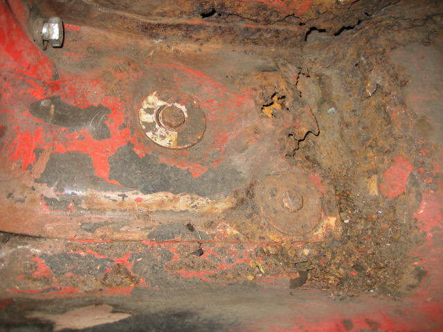
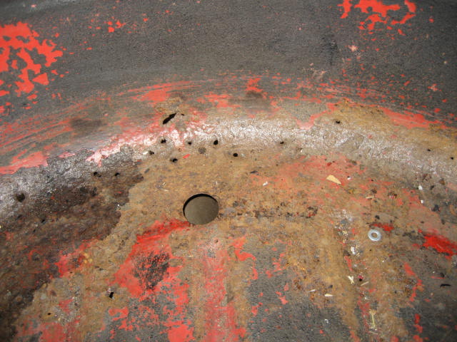
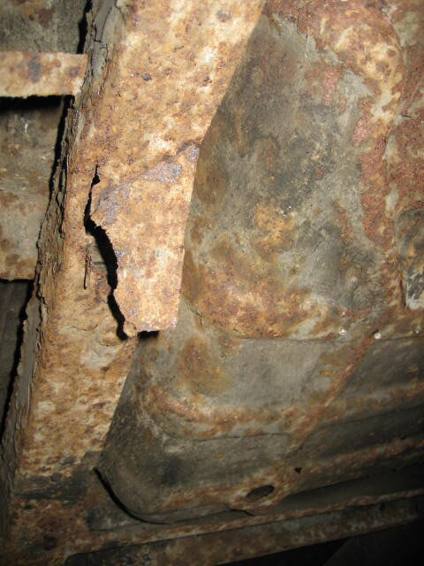
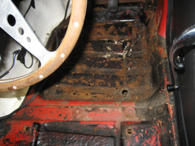
After inspecting the floor pan from the inside, there is definitely some work needs doing to repair rust spots and perforations, although the majority will simply need cleaning and painting. As with the underside.
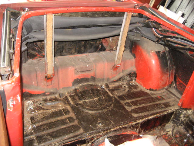
The more I see however, the more I am coming to understand that I have caught this car on the brink. Another couple of years exposed to UK weather would have most probably left this car’s body shell as scrap and too far gone to realistically restore. With this in mind I have decided to strip the car back to it’s shell and chassis and do the job properly.
After getting it home, an initial inspection has revealed the following:
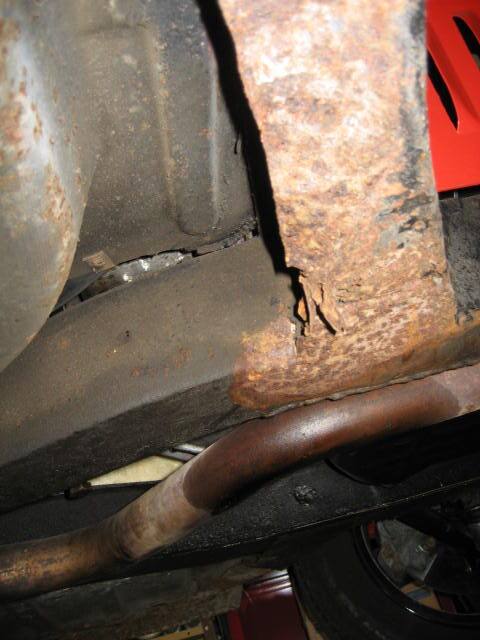
It seems a long list and I fully expect it to get even longer as I delve deeper, but this is what I expected for a 55 year old car that has seen many owners. I didn’t buy a one owner concours car. I bought a project.