August Bank Holiday weekend…….Rain, Rain, Rain
Not to worry, plenty to do in the garage…
I was away from home on business last week and had a quite evening where I took the opportunity to reacquaint myself with a few other Zero build blogs. Thanks to RichardL, Aidan and Dave S for sharing their experiences. The question I have yet to decide on is: side panels now or after the engine is in place?
At some point soon I will need to move the car (it’s starting to look and feel like a car now) from the high stands. It will need to sit on it’s wheels, at least for a short time, when this happens. The obvious point is for engine assembly and fit.
Drilling and securing the engine mountings with the side panels attached is not easy according to the blogs and access is far better with the panels off. I know GBS don’t do it this way, but they have experience of many, many installs and all tools and equipment at hand. I will have one shot and want it to be a simple and predictable as possible given this is the installation of the key component of the car. So my plan is to build up the front suspension without the side panels and not torqued up. Just sufficient for the car to sit on it’s wheels for a while and maybe roll in and out of the garage. There must be a photo opportunity there. I will in due course remove the front suspension and fit the side panels, but only after the engine is in.
So, decision made, it’s on with the building of the front suspension.
I have already populated the wishbones with nylon bushes and crush tubes. I have also already re-tapped the upper wishbone threads for the upper ball joint. So the next step was to bolt the wishbones and Gaz shocks to the chassis. As always, the powder coat needs to be removed from the pre-drilled mounting holes in the wishbones and chassis and any gaps between the chassis brackets and bushes, padded with washers for a “snug” fit.I have one query regarding the size of the washers supplied with the shock mounting kit. They are only just the same size as the nylon bush against which they press. Maybe these should be a little larger – need to check.
Next I built up the hub by adding the front mudguard support – again I had to remove some of the powder coating to allow this to fit together – don’t forget that these are handed so you need to get them the right way around (look for the notch).
The lower ball joint then bolts onto the lower wishbone. Here I tightened it with normal nuts and used the nyloc as a lock-nut. This will allow the joint to take the weight of the car but not destroy the nyloc before final installation.
As mentioned a few times across this blog, I may have a passion for engineering, but I am not an automotive engineer and this is my first build. So when I had assembled the upper and lower wishbones and surveyed the result I was a little perplexed. Even after a coffee, more contemplation and searches of several blogs I was still confused.
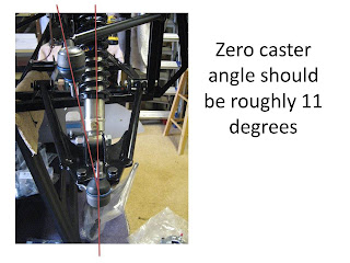
When I looked at the two ball joints they were not aligned, one above the other. When I looked at the hub the mounting points were aligned one above the other. I took some pictures and sent them up to Richard@GBS. A short phone call later revealed that all was well. For those that have experience in things automotive this is called the Caster angle, and should be roughly 11 degrees on a Zero. Here’s a better description ….
And if you are after further descriptions, I found this informative too…
Caster, tow and camber explained
The front brake calliper then bolts onto the hub. Another query here. As with the rear the supplied bolts protrude through the hub and touch the brake disk. A couple of washers fix this – see photo. Is this OK? – need to check.
Here the final assembled result
And here is the build as it stands. The firewall and scuttle are simply resting there – not fixed


