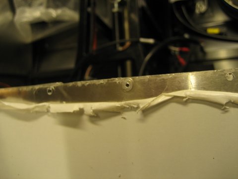
 Some time ago in my post Odd and Sods I looked into polishing the brushed aluminium rather than leaving as-is. I found the best finish could be obtained by using several applications of grinding paste with a mechanical polisher. The problem I found was that the finish was almost a stainless steel finish but not quite and was very difficult to get consistent across larger areas. So I decided on a less labour intensive approach that took the dullness off the metal surface, and left it looking like shiny aluminium. I found the best polish is Autoglym Metal Polish.
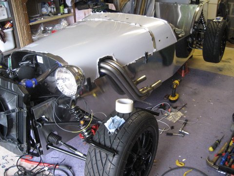
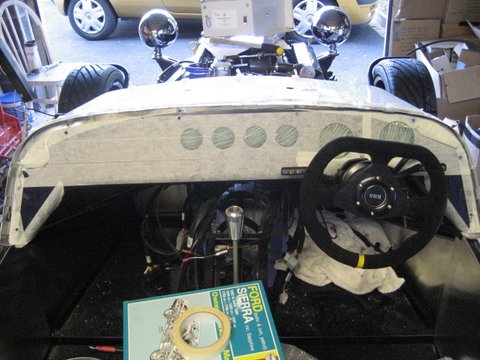
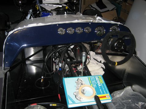
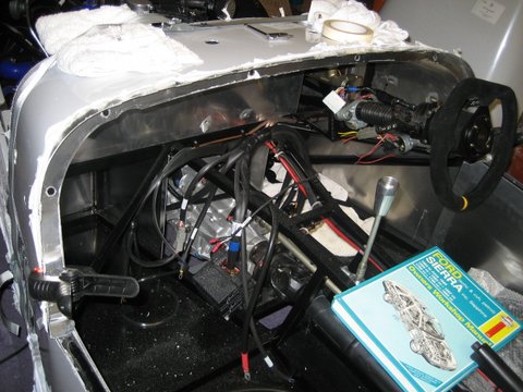
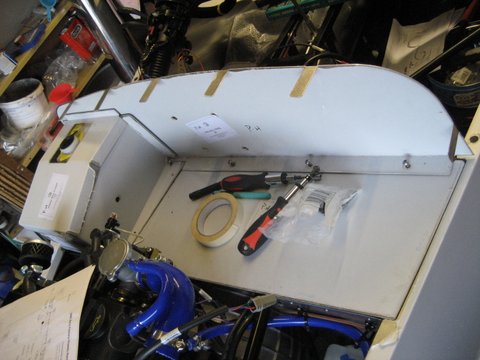
Before adding all the trim to the main body panels I am polishing them with Autoglym. I have done the near side panel and the back panel and I think the results look good. Ruth@GBS has agreed to source some decals to my spec for the sides and bonnet, which I think with compliment the shiny aluminium well.