Near-side Panel and Suspension

Nothing much to say about the near-side that hasn’t already been said for the off-side. The side panel went on fine – with a bit of fettling where it meets the back panel as I decided to build the back before the front. The suspension went back together without issue including IVA covers.

Whilst I had an open (and warm) tube of “black-glue” I thought I would bond the inner side panels. I decided not to rivet – these panels are not for strength or rigidity.

Front Suspension

Its been a few weeks since I worked on the zero. One weekend was spent in Derbyshire in a superb chalet with great spa facilities for my daughters 18th birthday. I great family weekend. But unfortunately my daughter is not well at the moment. She has been diagnosed with Anorexia – a truly awful condition. You can’t really comprehend the depth and scale of the physical and mental suffering this condition causes until you witness it at first hand. It is currently taking a huge toll, especially on my daughter, but also the rest of the family. No amount of support seems to be able to combat the torment that this disease delivers.
My Zero build is not a race and I am under no pressure to complete the car quickly, however it has now developed a further function, as a cathartic release for a few hours when I can. 
Last Sunday I did find some time where I could concentrate on the Zero and lose myself in the build for a few hours. The off-side panel was bonded and riveted a few weeks back, so I thought I would re-assemble the front suspension and fit the IVA covers.
The torque settings I had difficulty with. Having used the Haynes manual as a primary source, I then used the web to supplement this and common sense for the rest. When I asked GBS for the settings at the rear I surprisingly didn’t get a straight forward list. Perhaps for fear of liability, I don’t know. But I haven’t bothered to ask GBS for the settings for the front. The settings I have used are in the Torque Settings page. These are for my reference only. I don’t recommend these settings. As I have said before, it is not me that will be cornering hard in your car. You must decide the setting you use.
I also fitted the brake pads into the callipers and the braided hoses to the side panel. I did have a little issue with the retaining spring on the brake pads. I couldn’t find any information on how to assemble it, but eventually found a position that seemed logical, although it did keep shooting off.


Off-side Panel

With the engine in place, the next job is fitting of the side panels before final fit of the front suspension.
As I had chosen to fit the back panel first, I knew that the side panels would probably not be a perfect fit where they meet the back panel at the rear wheels. A couple of minutes with the shears soon solved this. 
To fix the side panels I have elected to only use rivets on the underside of the panel – where they can’t be seen. Where the chassis meets the panel I have used “black glue”. I am really impressed by this stuff and don’t believe the panel will move at all once it is cured. Seen in the photo on the right is the first stage of the process. I will bend and fix the rear portion after freeing the clamps from the front, once it has dried.

Engine – Part 4

GBS kindly sent the missing spacers and bolts via first class post. 36 hours later they turned up 🙁 Not GBS to blame, but our postal service which seems to be in steep decline….. but enough of that.

With the spacers and bolts supplied I bolted the engine mounts to the engine block and lowered the engine so that it just rested on the chassis but carried no weight. I had already mated the engine and gearbox and bolted them together once more. 
The final step is to centre the engine in the chassis by marking the mid-point on a chassis cross member and aligning it with the centre of the nut on the flywheel. The position of the holes on the chassis plates for the engine mounting brackets was then marked and drilled to 8mm. 
I found that one of the off-side bolts would have been too close to the chassis to get a nut on underneath so I drilled a new hole in the bracket and used that instead. My logic being that the slight weakening of the plate by drilling another hole was much less of an issue than leaving one bolt off altogether.
As the engine can be hoisted vertically using this method of installation it was simple to move it out of the way to drill the plates. 
With the chassis plates drilled, it was now time to finally fit the engine and gearbox and torque up the bolts on the gearbox mount, prop shaft, gearbox casing and engine mounts (see Torque Settings). Finally with the side panels still off I fitted the started motor. Not the simple 5 minute job I thought. The top bolt is too close to the gearbox housing to tighten properly. After a few minutes filing down the rim of the nut head, it went in.

Engine – Part 3

Beautiful sunrise this morning.


I spoke to the guys at GBS yesterday about how to install an engine and gearbox on my own. There are two methods. The first is to mate the engine and gearbox and fit both as a single unit. This is difficult on your own but not impossible. The difficulty is the weight of the combined unit and manoeuvring it into the chassis opening whilst it dangles from the crane. The second is to fit them separately: the gearbox first and then the engine. The latter is simpler on your own because the gearbox can be positioned manually and the engine can go in almost vertically on the hoist. 

I decided to fit them separately.
First I needed to remove some gearbox casing from the base and bottom corner, and check that the clutch is aligned properly after fitting the spigot bearing. To do this I fitted the two spacers to the gearbox casing and mated the engine and gearbox, bolting it together so that it can be lifted as a single item. The engine spline slid straight into the gearbox and spigot without problem. With the unit dangling on my crane I marked the areas of the casing that needed to be removed. 
After a few minutes with my 9 inch angle grinder, both areas had been removed.
Next the gearbox mount must first be fitted. It requires a little reshaping first of all, followed by drilling the new mounting holes to 8mm. It is then installed from below – fully tightened and thread-locked.

With the gearbox lifted from underneath with my trolley jack, I eased it into place on the mounting and finger tightened the 3 bolts to the prop shaft.

Now the gearbox is in place (approximately) the engine can be dropped in from above vertically.  Having already ensured that the gearbox and engine go together easily, it didn’t take long to drop the engine in and mate it with the gearbox once more. Quite straight forward really. Then I found the problem. I didn’t have the fixing kit that connects the engine mounts either to the engine or the chassis plates. It was all going so well. As Newark is a 3 hour round trip, I called GBS and they kindly agreed to put the packs in the first class post – maybe tomorrow……..

Engine – Part 2

With the new sump assembled and ready, it was time to take the old one off – not that it had ever been used. First – drop the oil. As the temperature was only 4 degrees today it took a while. I thought about saving it for re-use, but it has been in there since 2004 so thought better of it. The filter took a bit of time to remove as its rubber seal had stuck to the engine block. 

Removing the bolts holding the sump to the engine block is the not the whole story. Whilst these bolts form the uniform pressure across the gasket, in order to remove the sump there are 2 more bolts that need removing. These are only accessible if you remove the steel tray at the base of the sump. They hold the oil feeder pipe in position. Another thing I learned (the hard way – laying under an oil dripping engine block) was that these bolts have star and not hex heads.

With the old sump finally off, I cleaned the sealant from the engine block and added new sealant to the outside rim of the new sump between the gasket and the edge of the machined surface. This should give that extra bit of protection. I then used a trolly jack to offer up the new sump to the block and bolted back in place.

Gearbox Prep

There are a few jobs that need doing to the gearbox before it is fitted to the engine block. 


Firstly the pin to which the clutch actuator arm connects, needs to be replaced with the longer one supplied by GBS. This is a very simple procedure of knocking out the old one from the rear and tapping the new home into place with a wooden drift.
Next there is the fitting of the quick shift gear lever. Again a simple job. The linkage is held together by pin secured by a rubber washer and the mounting bracket by bolts to the gearbox housing (torgued to 45nm and threadlocked). Just need to make sure that the collar on the universal joint is adjusted so that all gears can be selected before everything is tightened up.


Raceline sump

 The Raceline sump was a real pleasure to assemble. For a third party after-market product it is an extremely well made piece of engineering, even down to the flexible gasket which fits into a machined recess around the top.
This is one of the only assembly jobs on the  build so far where instructions are supplied. The trickiest bit is inserting the oil feed pipe once the rubber washers are in place. It is a really tight fit and difficult to push home. Other than that, the unit goes together very well. Here it is complete and semi wrapped before being put on one side awaiting its bolting to the engine block.

Spigot Bearing

In order to run a transverse engine in-line, a spigot bearing is required to be installed. To do this the clutch pressure plate and clutch need to be removed, before installing the bearing. The bearing needs to be tapped into place with a hammer and a wooden drift making sure that the finger bearings are at the back. Then re-install the clutch and pressure plates making sure the clutch plate is aligned properly.
Forget this small bearing and your gearbox is scrap within a few hours on the road.

Engine – Part 1

Now it’s time to start the mods to the Zetec. The first few minor jobs are the removal of the inlet and outlet manifolds in preparation for the install of the GBS units.
First to be removed was the fuel injectors and fuel rail, followed by the manifold itself. 

You can see in the photo the cut-down manifold from GBS at the bottom of this picture. They have a jig to cut down the original inlet manifold to this size. I will return the old/full manifold back to GBS this week when I go up for a quick visit. I want to talk through the engine install before I start in earnest.

Each of the gaskets has to be transferred to the GBS cut-down version before it is installed once more along with the fuel rail and injectors.
The IAVC is also mounted on the old manifold. I have decided to remove it and try and use it with the Emerald ECU and the GBS prototype I purchased from Richard Lincoln. Richard originally bought it from GBS, but then decided to design and build his own. I am not going to do anything with it at the moment but will keep it ready for install when the time comes.

Here is the engine with the new manifold installed. I have taped up the inlets to prevent anything getting in there that shouldn’t.
Finally, the exhaust manifold needs to be removed. I am not sure if GBS can recycle this in a similar way to the inlet manifold. I will take it up with me and find out. The heat shield can be re-used along with all of the fixings. Again I have taped the port openings. This photo also shows the installed GBS breather blanking plate which replaces the Ford breather unit.

Rear Panel Complete

Work has been pretty hectic of late and has unfortunately eaten into my weekends, but this weekend I managed to spend a few hours in the garage. My focus was the back panel. It has been on and off a few times as I sorted out how it should fit and then how it should be fixed. This weekend I decided I had thought enough and it was time to do.
After finally figuring out that it was the distance between the bracing arms and the lower chassis that was the cause of my inability to make the panel fit correctly, I then focussed on the underside. I trimmed a few mm from the panel where it was touching the diagonal chassis members but that was it. I carefully marked the chassis position on the outside of the panel – double checked – triple checked and the drilled some pilot holes. When I was sure I had the correct position I very gingerly drilled the remaining holes in the panel and through the chassis powder coat only. As the fuel tank is so close, I removed the panel again to complete the drilling of the chassis and de-burr the panel.
I followed a very similar procedure with the drilling of the rivet holes for the sides. With clecos in the already drilled base and the panel clamped in position, I marked and drilled the pilot holes, removing the panel again to complete the process. You will also notice from the photo the outline of the rear wheel arch which I very crudely applied so I didn’t put any rivet holes in visible places where it wasn’t necessary. 
With the back panel now clecoed in place I then positioned the boot in-fill panels, marked and drilled these too for their fixing to the chassis only. Be careful drilling into the tubular chassis members. The drill bit can twist and shear if the drill is not pointing directly at the inner centre of the tube. That little piece of experience cost me two cobalt drill bits 🙁
With all of the preparation complete it was time to open another tube of “black-glue”. With a bead applied to all areas of the chassis where the back panel and boot in fill panels touched, I clecoed the panels back in position and got the riveter out.
I left it to cure over night before marking and drilling the boot infill panels to the rear panel and the rear panel base to the rear panel sides. Then it was “black glue”, clecos, and riveting to finish the fixing. 
Back panel finally on and secured – another milestone.
Whilst concentrating on making sure I got the back panel right I missed one simple but important step. BEFORE FINAL FIXING OF THE REAR PANEL MAKE SURE YOU ROUTE THE WIRING LOOM FOR THE REAR LIGHTS THROUGH THE HOLES IN THE REAR PANEL. As I found out, if you try and do this afterwards – you can’t. There is insufficient space between the rear panel and the tank. I had to remove the spade terminals from the wiring loom to get the wires through. I then needed to attach some more spade terminals. Not a big issue, but easily avoidable.
I had already cut down the rear lights so that they will sit at 90 degrees to the road, so with the re-assembled loom in place I attached the rear lights and the petrol filler cap. She’s starting to look something like a car now – at least from the back.
The next job on my list will be the engine preparation and fitting so I can finally get the side panels on. When I picked up the kit and got it home, I put the engine at the top of my garage – out of the way. Having now build the car in front of it, I can’t get the hoist anywhere close to move it. So, it was time to put the wheels on and lower her carefully to the floor and out on to some tarmac for the very first time.

More back-panel

I’ve been thinking about the fit of the back panel on and off all week – something wasn’t right. Took another look this morning and again, there was definitely something amiss. In order to get the side panels (over the shocks) to line up, even roughly under force was very difficult.

So spent an hour with a fresh ground coffee and a laptop scouring blogs. A number of the recent and well illustrated blogs are for the GT chassis which has a different arrangement of panels at the back. But then I found it….. and it was (as usual with these things) as obvious as the worry lines on my forehead. The two stays linking the roll-bar to the back-panel were neither level nor the correct hight above the rear chassis. As I don’t know what the correct height is, I adjusted them (brute force) bending them upwards slightly each time, keeping them level until the back panel fitted properly. Much better now. So much so I have started to drill the rivet holes for the final fixing.
I did get distracted at one point when I noted the proximity of the fuel tank to the mounting points for the rear warning lights. Would there be sufficient room for a rivnut? So before I permanently riveted and bonded anything I widened the mounting holes to 9mm and popped some rivnuts in. Then I needed to cut down the rear cases on the lamps for IVA before I could check that they all fitted together without snagging on the tank. I took 8mm of the back of the lamps with a fine toothed hack saw and used some IVA trim to tidy up. They now fit at 90 degrees to the road.
My work and home life have limited progress this week. Maybe I will book a week off soon and make some progress.

Rear panel – first attempt

I have not been looking forward to this element of the build, but it has to be done.
Looking at the outer radius of U-shaped rear shroud, I found a piece of 6″ sewer pipe (un-used) with roughly the same radius. Surely it was a simple matter of bending the panel around the pipe?
Having done this and presented the rear panel up to the chassis, I found that it wasn’t such a simple process after all. The radius of the bend at the top of the panel was simply not tight enough and if I tried to tighten it the panel didn’t fit around the rear uprights. I tried a number of bends but the panels needs to fit close to rear chassis member which limits movement.

Add caption

In the end I removed the first tab from each side of the upper part of panel where it meets the chassis over the coil springs. This has allowed the radius to shrink under the shroud but I think I may be be saving up another problem as the panel doesn’t seem horizontal where it will eventually meet the side panels. I hope it will pull up as I rivet it all together. Finally today I applied the IVA trim to the rear shroud. The instructions on the GBS web site are contradictory here. They say that the broad tadpole trim is used on both side of the shroud, but also the small edge trim should be used on the internal edge. Having checked by reference photos of factory built cars it looks like the broad tadpole trim is used for the outer edge and the small edge trim for the internal.


Fuel tank and boot space

The last few weekends have been busy ones. I have a rather large hedge around both front and rear gardens that needs cutting at least twice a year. I couldn’t put this off any longer. And there is Finlay the springer spaniel who wants to play for as long as you will throw a ball for him. And finally there is my job that is infringing into my weekends of late (but hopefully only short term).
However, that said I did manage a few hours in the garage this weekend. 
With the car still up on high trestles I thought I would do some more on the boot space and get the fuel tank finished. I started by tidying the cables and pipes making sure nothing was going to dangle or potentially get caught in the rotating drive shafts. I specifically anchored the return fuel pipe to the chassis with a couple of cable ties just in case the IVA inspectors torch shone in that direction. 
Next I filled the diff with oil. A trivial job with the car in the air and no back panel on, but I suspect much trickier later on. 
Then it was the turn of the in-fill panels. I marked up and drilled the triangular panels each side and held them with clecos for now. I have found that the “black glue” solidifies in the tube after a few weeks if not used, so I will wait until a few panels that need bonding before I open another one. 
The maintenance hatch has been cut to fit the hole between the chassis members, but once the triangular in-fill panels are in place the panel will be unable to be removed upwards. There’s no point in a maintenance hatch that can’t be opened, so I have trimmed the hatch panel such that it can be removed vertically from inside the boot space and held it down with 4 rivnuts rather than rivets.
Having now done as much as I can here, I finally bonded in the fuel tank centrally to the chassis, using the “black glue” from a tube I cut in half, so as not to waste it, since the nossle and front of the tube were blocked.

Seats and fuel tank

So, where next? 

  • I can continue building the rear of the car right up to rear lights.
  • I can make a start on the engine and gearbox prep

As I have found so far, some jobs can be done to a point and then have to stop to wait for something, like a tap or a washer or just inspiration. So I think I will just continue down both avenues in parallel. That way if one stalls I can make progress on the other.
In order to start on the engine it needs to be moved and that involves moving the car first and dropping it down to axle stands. I need to source the axle stands first.
So, on with the rear. The fuel tank sender is the next job. Having marked up the position for the pilot holes for the self tappers, I drilled 3.2mm holes and tried valiantly to catch the swarf before it disappeared into the fuel tank. I then swilled out the tank with some fresh fuel before coating the gasket with some Locktite 5922 and putting it all together. Left it to harden off.

While the car is still at a comfortable working height, I thought I would position the seat runners ( and it was a good excuse to see the seats in the car for the first time). 
It is difficult to mark positions on the black powder coat, so the first step was to cover the floor with paper and then mark the position on the runners on the paper. As each runner has a nyloc between it and the floor, I used some waste wood as a spacer, which also prevented any scratches. 8mm holes drilled, I decided to mount the seat runners upside down on the base of the seats. Structurally I couldn’t see any reason why not, and the fixing bolts are much easier to get at this way around. As the seats are coming out again to fit the internal panels etc I used standard nuts rather than the nylocs. 
There doesn’t seem to be much tolerance between the seat edges and the side panels / central tunnel – snug. I may have to alter the seat runners slightly once all the panels are on.


Steering Rack

The tap for the rusty steering rack extensions came during the week. Just a few minutes work to clean the threads and assemble the ball joint. Logic told me that the ball joint should enter the hub from the top. Should the nyloc work free, the steering will at least be connected by gravity and the morse taper. When it was obvious that the ball joint did not fit from the top I doubted whether I had fitted the hubs to the right sides of the car. Checking my reference photos I found that the ball joint enters the hub from underneath, so nothing wrong with the construction – just seems an odd way of doing it.
Having finished the steering rack assembly I adjust the distance from the back of the lock nut and the centre of the top ball joint to approx. 48mm and the steering rack extensions so that the wheels point straight. The clearance below the steering rack gaiters either side is very tight. Only a couple of millimetres. But it is clear – just.
As the side panels are not on yet, all this will have to come off again, so I have not tightened any of the nylocs and non of the IVA plastics have been installed. I now have all 4 corners built and the steering working. Pretty much a rolling chassis.

Donnington

No progress on the build this weekend. A new addition to the family has occupied all available time today.


I did manage a great day at Donnington Park yesterday though. There were many Zeros on show both on the GBS stand and also in the RHOCar enclosure. Managed to speak to a number of Zero builders, all keen to explain the hows and whys. I really do like this aspect of kit car building. 
You may have seen from earlier posts that I have been trying to decide how I should finish the exterior of my car. I decided this weekend thanks to the Donnington show. I spoke with 2 owners who had polished their aluminium panels, and was able to see the end result and talk to them about how it was achieved. I learned that Auto Glym Metal Polish is the stuff to use. Having tried it today I agree. It doesn’t produce the mirror effect I came close to with specialist metal polishes and power tools, but occupies an understated middle ground between high polish and the brushed matt. The problem I had with the high sheen was three fold: firstly it was very effort intensive; secondly it would be difficult to get a consistent finish across such a large area; and finally it would never be a stainless steel finish, so it would always look like a scratched version of stainless to the novice eye. Decision made.
I also picked up a battery isolation switch from the show. I am not looking to install it so that I can go racing, but as a security feature under the dash somewhere.

Odds and sods…

Went to the Matthew Street Festival in Liverpool yesterday. Such a great atmosphere and so many people just there for the music and the sunshine. Today its raining again. What do you expect for August Bank Holiday. So tried to spend a little time in the garage around some home chores and family business.
First thing was to install the steering rack. Quite straight forward having already shortened and painted the U-bolt. Mounted it mid-to high on the brackets to give a much clearance as possible over the lower front wishbone mountings. Then opened the bag containing the rack extensions. As you can see the thread inside the extension tube is corroded which prevents the extension screwing onto the rack any further than 10mm to 15mm. An M14 x2 tap has been ordered to clean the threads. I am sure GBS would do it for me if I asked but a new tap is £7.50 delivered which is far cheaper than as 120mile round trip to Newark.

I am still undecided as to the final look of the external aluminium. Should I simply leave as is; paint it; wrap it or polish it. I tried the “polish it” option on the top of the boot infill panel. As you can see, you can get quite a good finish with metal polish and an electric drill attachment.
Finally today I placed the internal panels around the chassis to see how it all fitted together. No sure about the boot infill panels below. They seem to have been bend at the wrong angle.

Update 29th Aug 2012: Yes. After an email conversation with Richard@GBS today, the panels need to be bent back to fit flush with the top of the petrol tank. 
Whilst fiddling with these panels, the brake pipe T-junction caught my eye again. When I put some tension on the hand-brake cables after fitting the rear callipers, I noticed that the brake pipe was very close to the hand-brake cable adjuster. I decided tonight that it was too close and moved the mounting mount up a few millimetres. There is very little tolerance for movement here. Behind the mounting place is a chassis bar and you can’t drill into this bar because there will not be sufficient clearance for the brake light sensor to sit under the boot floor.

Front suspension

August Bank Holiday weekend…….Rain, Rain, Rain
Not to worry, plenty to do in the garage…

I was away from home on business last week and had a quite evening where I took the opportunity to reacquaint myself with a few other Zero build blogs. Thanks to RichardL, Aidan and Dave S for sharing their experiences. The question I have yet to decide on is: side panels now or after the engine is in place?
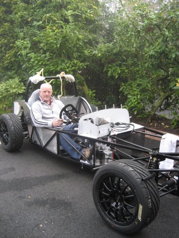
At some point soon I will need to move the car (it’s starting to look and feel like a car now) from the high stands. It will need to sit on it’s wheels, at least for a short time, when this happens. The obvious point is for engine assembly and fit. 
Drilling and securing the engine mountings with the side panels attached is not easy according to the blogs and access is far better with the panels off. I know GBS don’t do it this way, but they have experience of many, many installs and all tools and equipment at hand. I will have one shot and want it to be a simple and predictable as possible given this is the installation of the key component of the car. So my plan is to build up the front suspension without the side panels and not torqued up. Just sufficient for the car to sit on it’s wheels for a while and maybe roll in and out of the garage. There must be a photo opportunity there. I will in due course remove the front suspension and fit the side panels, but only after the engine is in.
So, decision made, it’s on with the building of the front suspension.
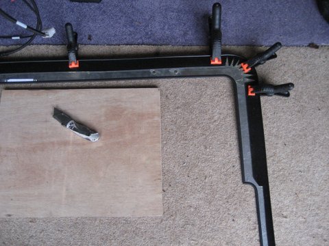
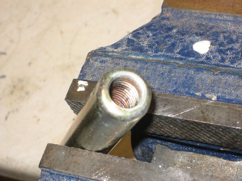
I have already populated the wishbones with nylon bushes and crush tubes. I have also already re-tapped the upper wishbone threads for the upper ball joint. So the next step was to bolt the wishbones and Gaz shocks to the chassis. As always, the powder coat needs to be removed from the pre-drilled mounting holes in the wishbones and chassis and any gaps between the chassis brackets and bushes, padded with washers for a “snug” fit.
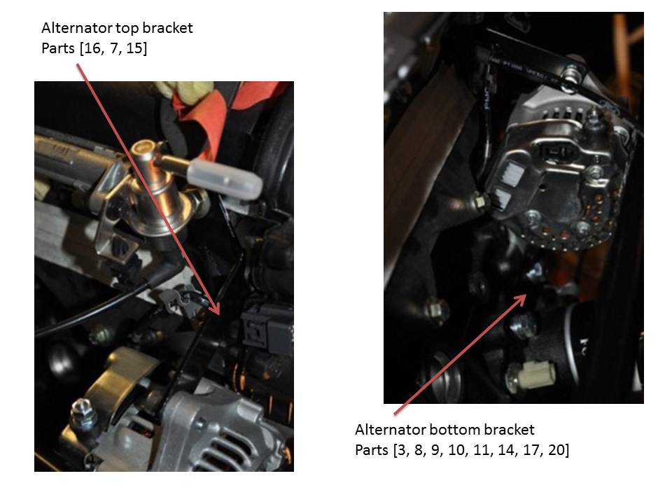
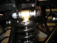
I have one query regarding the size of the washers supplied with the shock mounting kit. They are only just the same size as the nylon bush against which they press. Maybe these should be a little larger – need to check.
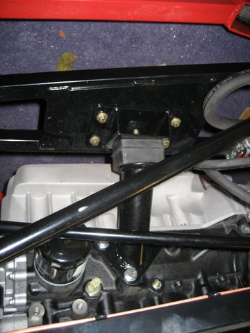
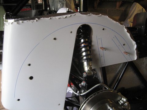
Next I built up the hub by adding the front mudguard support – again I had to remove some of the powder coating to allow this to fit together – don’t forget that these are handed so you need to get them the right way around (look for the notch).
The lower ball joint then bolts onto the lower wishbone. Here I tightened it with normal nuts and used the nyloc as a lock-nut. This will allow the joint to take the weight of the car but not destroy the nyloc before final installation. 

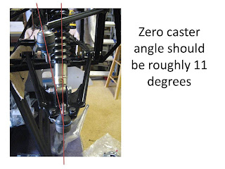
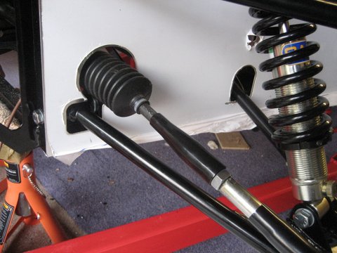
As mentioned a few times across this blog, I may have a passion for engineering, but I am not an automotive engineer and this is my first build. So when I had assembled the upper and lower wishbones and surveyed the result I was a little perplexed. Even after a coffee, more contemplation and searches of several blogs I was still confused.
When I looked at the two ball joints they were not aligned, one above the other. When I looked at the hub the mounting points were aligned one above the other. I took some pictures and sent them up to Richard@GBS. A short phone call later revealed that all was well. For those that have experience in things automotive this is called the Caster angle, and should be roughly 11 degrees on a Zero. Here’s a better description ….

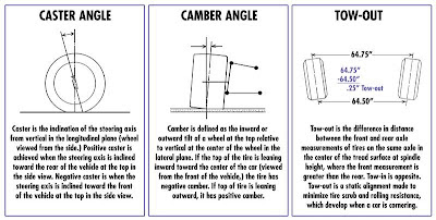
And if you are after further descriptions, I found this informative too…
Caster, tow and camber explained


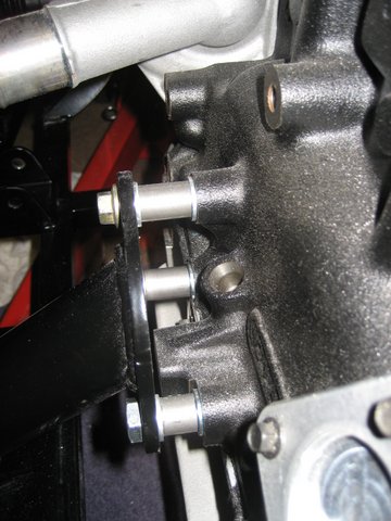
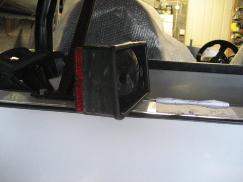
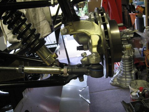
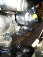
The front brake calliper then bolts onto the hub. Another query here. As with the rear the supplied bolts protrude through the hub and touch the brake disk. A couple of washers fix this – see photo. Is this OK? – need to check.
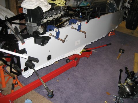
Here the final assembled result

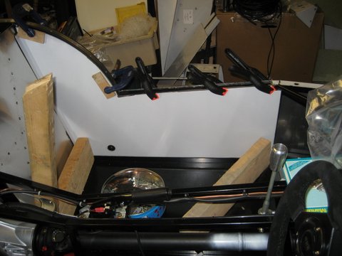
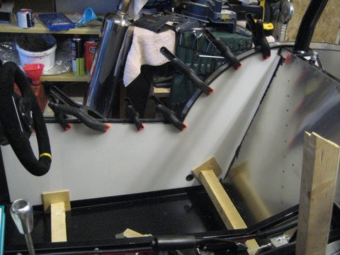
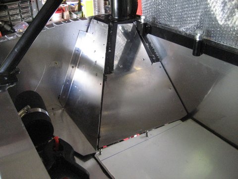
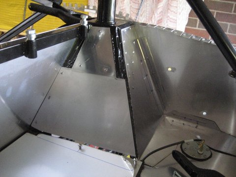
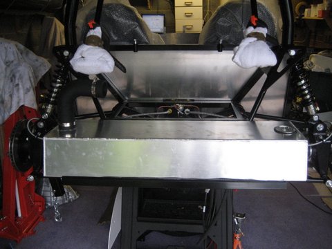
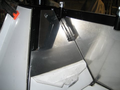
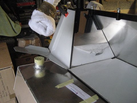
And here is the build as it stands. The firewall and scuttle are simply resting there – not fixed

Rear suspension – almost final

I drove up to GBS again yesterday to collect my wheels and tyres, recon gearbox and diff breather pipe. All were awaiting collection – thanks Richard@GBS. The wheels look excellent having now been clothed in Yokahama 195/50 R15 rubber.
Whilst I was there I walked through the torque settings for the front and rear suspension – see Torque Settings.

Today I tightened up the rear, cut down the hub plate to calliper fixing bolts and assembled the callipers. I have found another snag here that I need to talk to GBS about. Once the calliper fixing bolts are tight, the calliper itself touches the brake disk. Same on the other side. I have either assembled something incorrectly or I will need to grind down the hub bracket by 1mm to 2mm to bring the brake disk into the center of the calliper. 
[Postscript – 20th Aug 2012: Guidance from GBS was to remove the powder coat down to bare metal at the ends of each bracket. This done there was still insufficient gap on the off-side so I needed to remove a little more. The disks now spin clear and even within the calliper.]

I spent quite a bit of time scratching my head over this, which has limited my progress this weekend, but I did manage to tap the front upper wishbones. The threads in both were full of powder coating and refused to accept the ball joint. I ordered a M18 1.5 tap from Hong Kong which came on Friday. All is now clean and the ball joints spin down the thread unimpeded. Another oddly satisfying problem resolution.