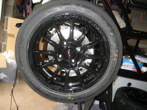
I drove up to GBS again yesterday to collect my wheels and tyres, recon gearbox and diff breather pipe. All were awaiting collection – thanks Richard@GBS. The wheels look excellent having now been clothed in Yokahama 195/50 R15 rubber.
Whilst I was there I walked through the torque settings for the front and rear suspension – see Torque Settings.

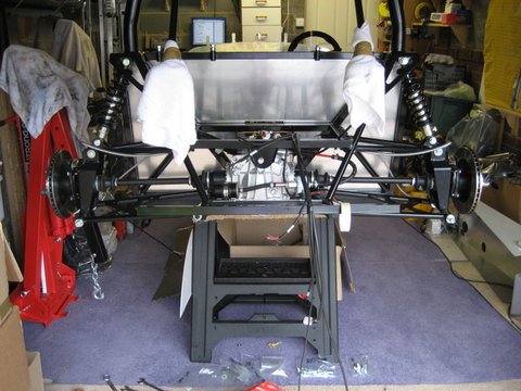
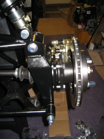
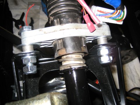
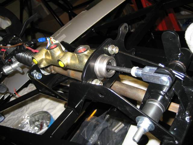
Today I tightened up the rear, cut down the hub plate to calliper fixing bolts and assembled the callipers. I have found another snag here that I need to talk to GBS about. Once the calliper fixing bolts are tight, the calliper itself touches the brake disk. Same on the other side. I have either assembled something incorrectly or I will need to grind down the hub bracket by 1mm to 2mm to bring the brake disk into the center of the calliper.
[Postscript – 20th Aug 2012: Guidance from GBS was to remove the powder coat down to bare metal at the ends of each bracket. This done there was still insufficient gap on the off-side so I needed to remove a little more. The disks now spin clear and even within the calliper.]
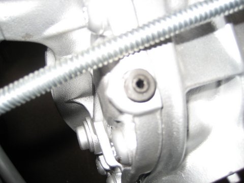
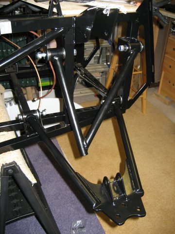
I spent quite a bit of time scratching my head over this, which has limited my progress this weekend, but I did manage to tap the front upper wishbones. The threads in both were full of powder coating and refused to accept the ball joint. I ordered a M18 1.5 tap from Hong Kong which came on Friday. All is now clean and the ball joints spin down the thread unimpeded. Another oddly satisfying problem resolution.