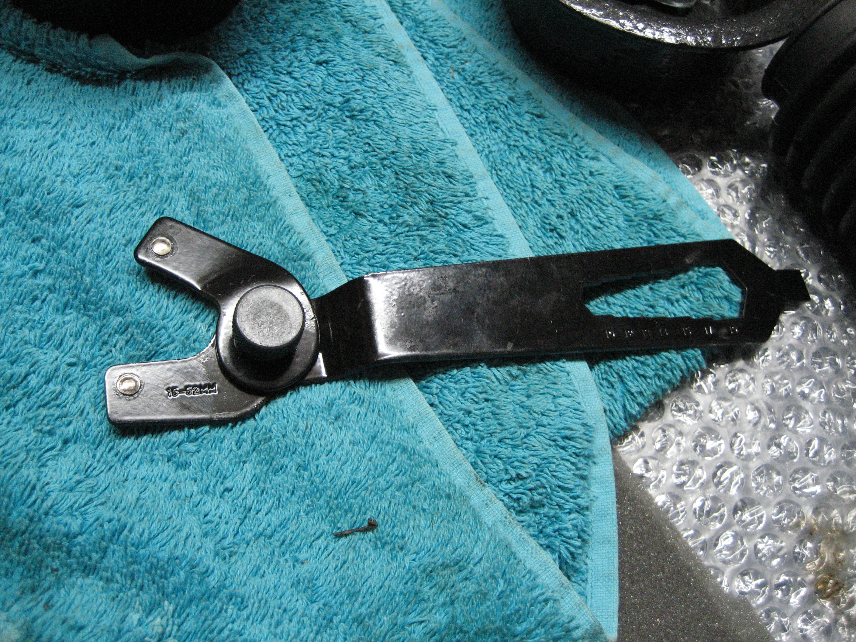
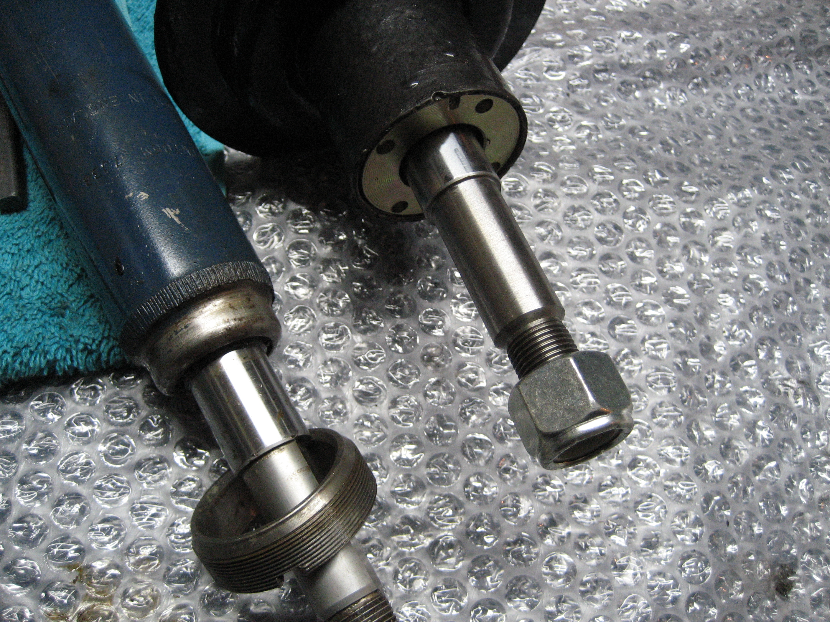
Adjustable Pin Wrench
First thing this morning I made the call to MachineMart to check the stock levels for their adjustable pin wrench. Their customers services said they would check the closest store in Wolverhampton and phone me back. After lunch – still no call so I phoned their Wolverhapton store direct – no stock. So I phoned their Stoke store – again no stock. MachineMart – if you want to sell things you need to stock things people want to buy or they will simply buy from elsewhere. So I found one in Toolstation (Toolstation Pin Wrench) in Cannock. 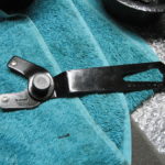 Their website helpfully gives details of stock levels and their customer service was very good – so much so I ended up buying 2 other items as well as the wrench:
MachineMart – 2 stars; Toolstation – 5 stars.
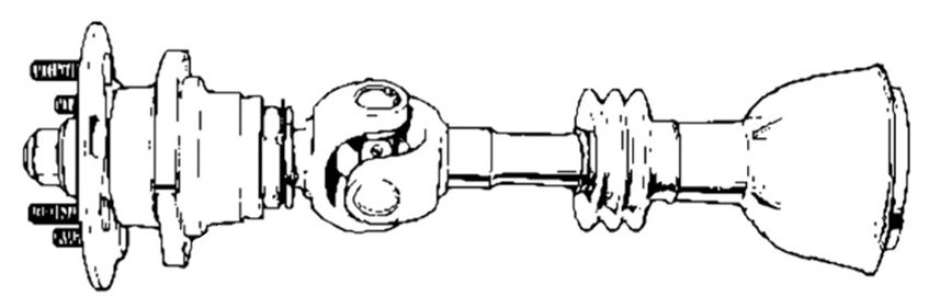
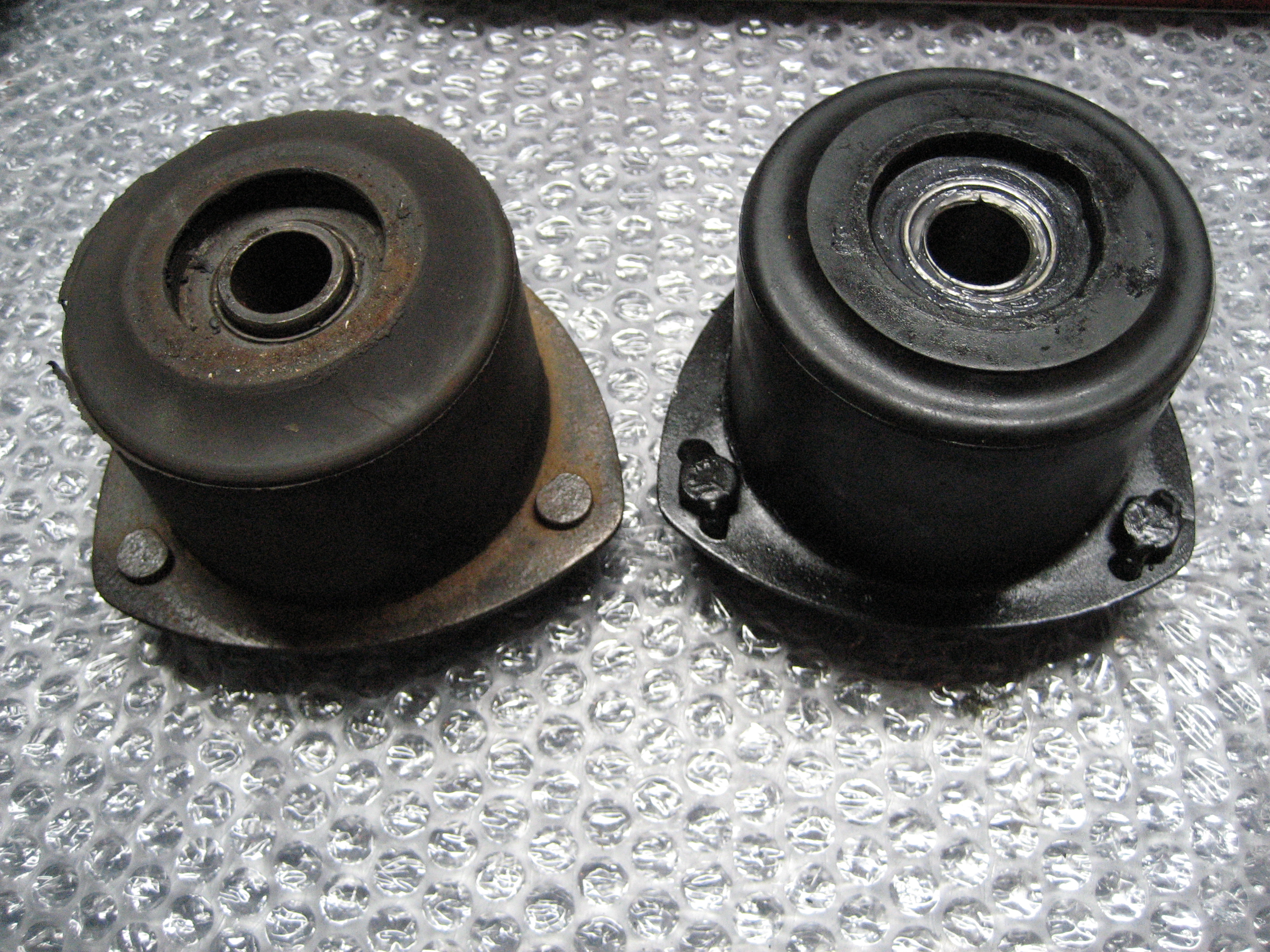
Front Strut Assembly
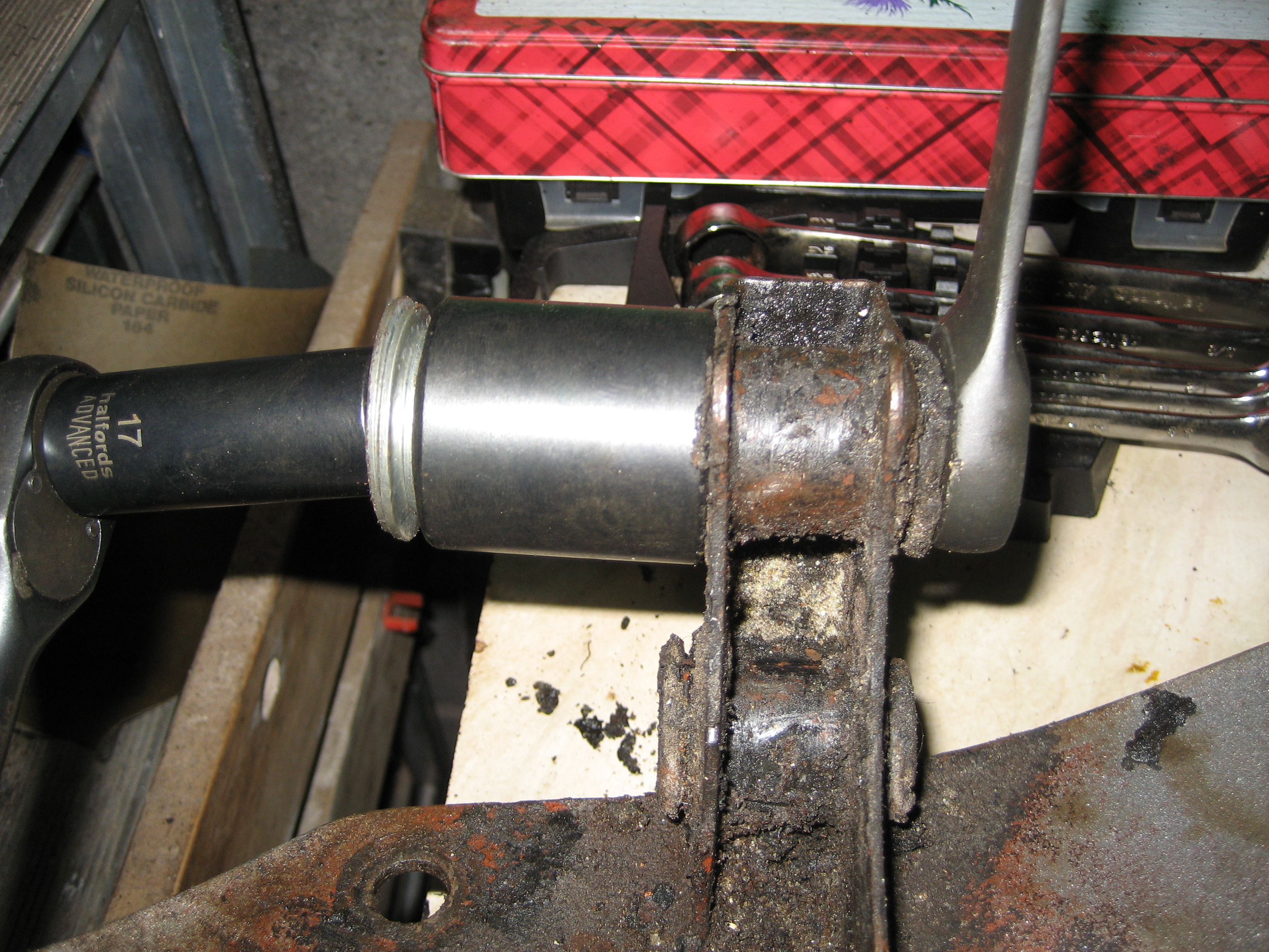
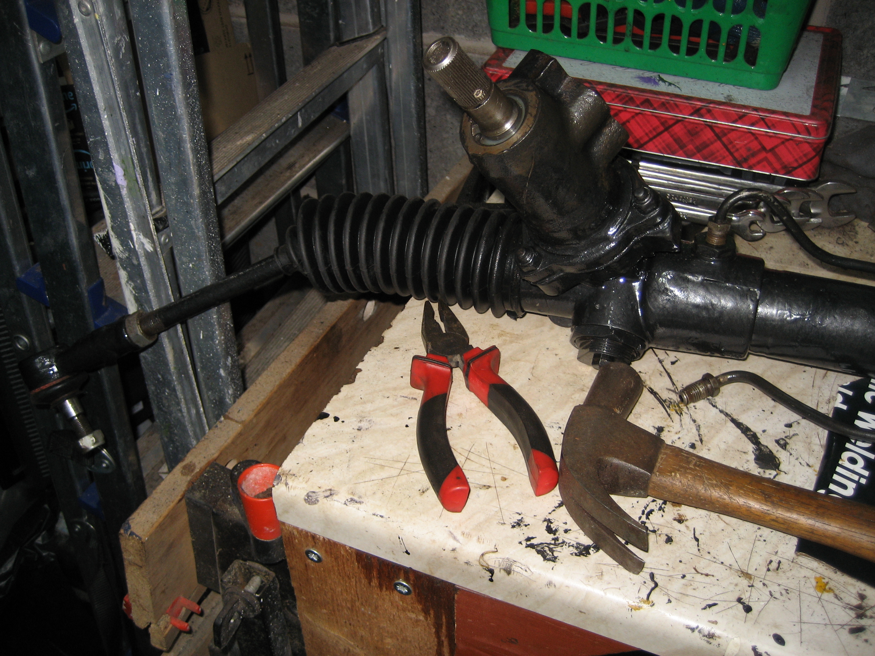
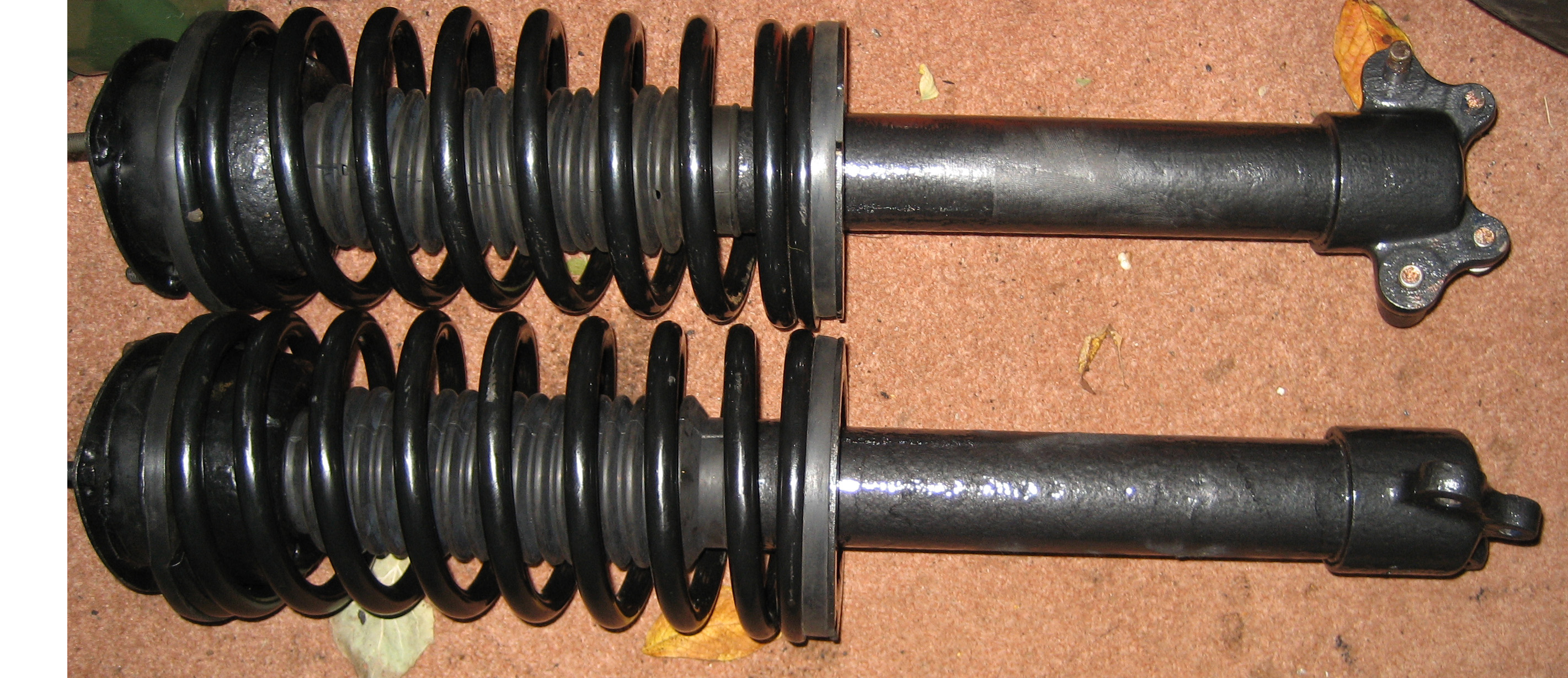
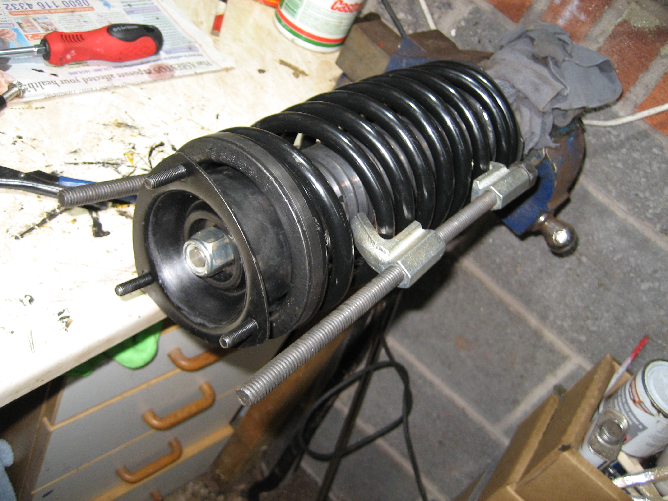
Using the pin wrench I was quickly able to tighten the strut insert into the strut itself and then on went the nice new clean gaiter. Now the slightly scary bit – compressing the spring to 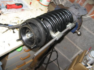 allow the front spring upper seat pan and strut top mounting to be threaded onto the strut insert. As well as the variuos washers and the top and bottom spring insulators. I was surprised just how much I needed to compress the spring in order to finish the assembly. Trying not to think of the energy I was forcing into the spring steel and what would happen if the spring compressors gave up.
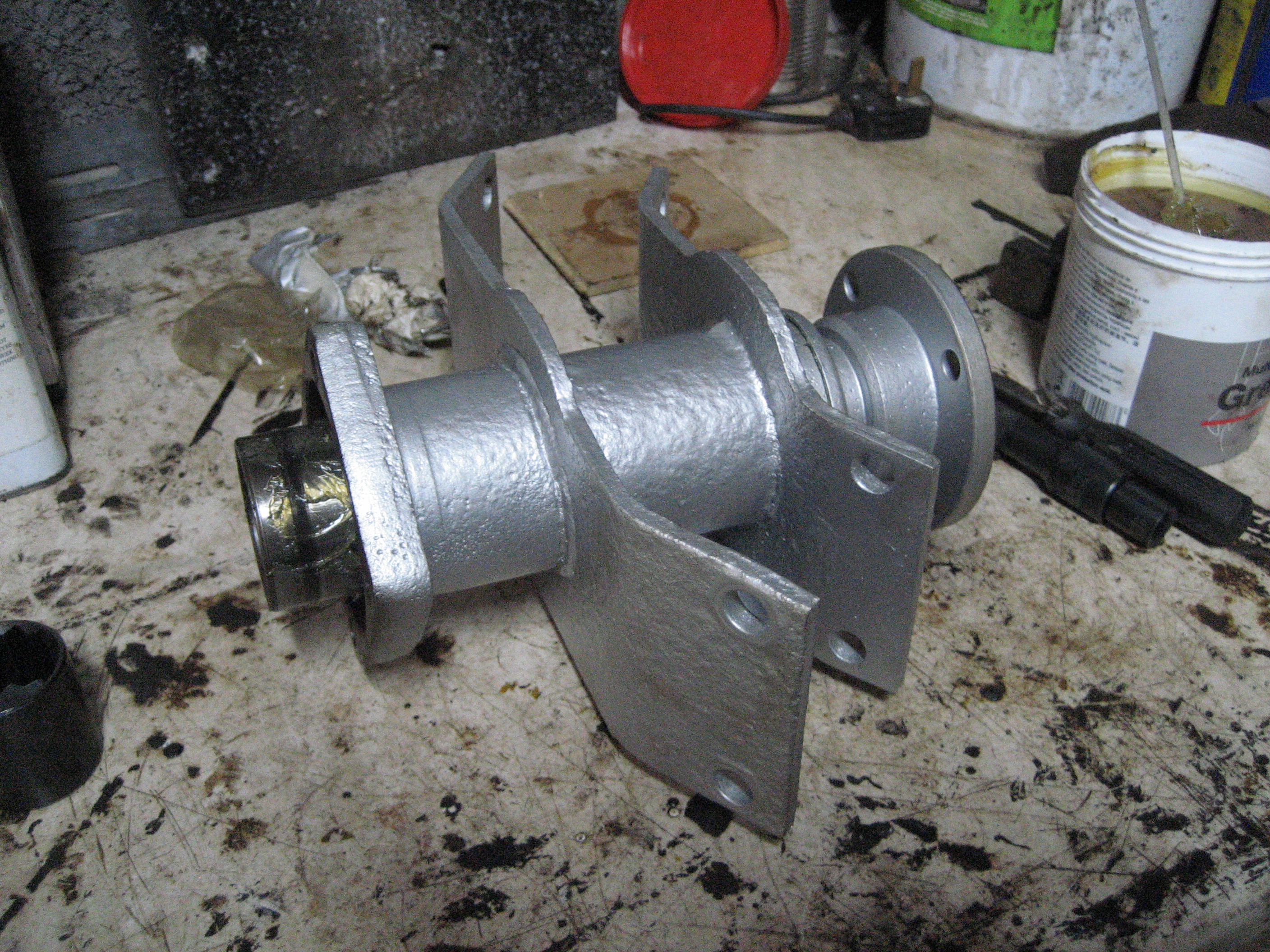
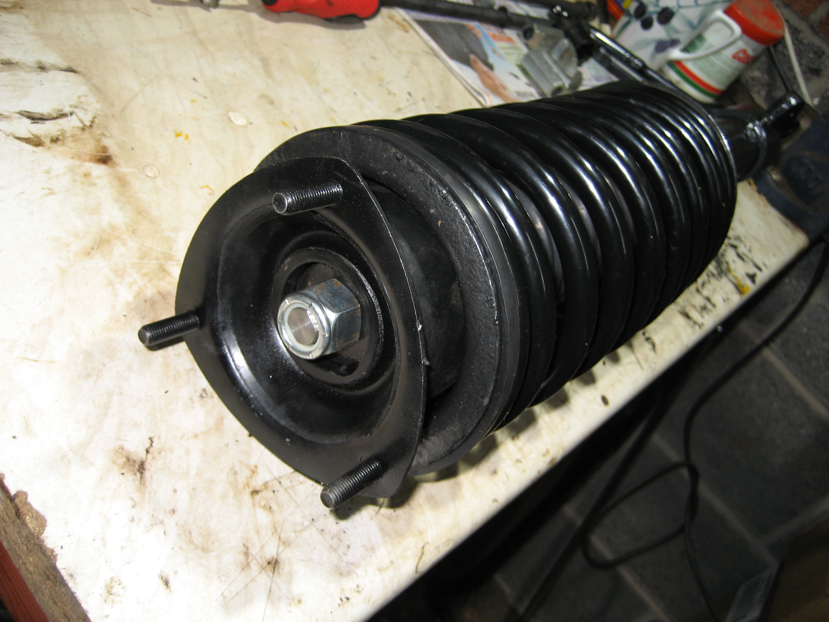
Then the new nyloc was in place and the strut assembly was complete – I’m very pleased with the end result.

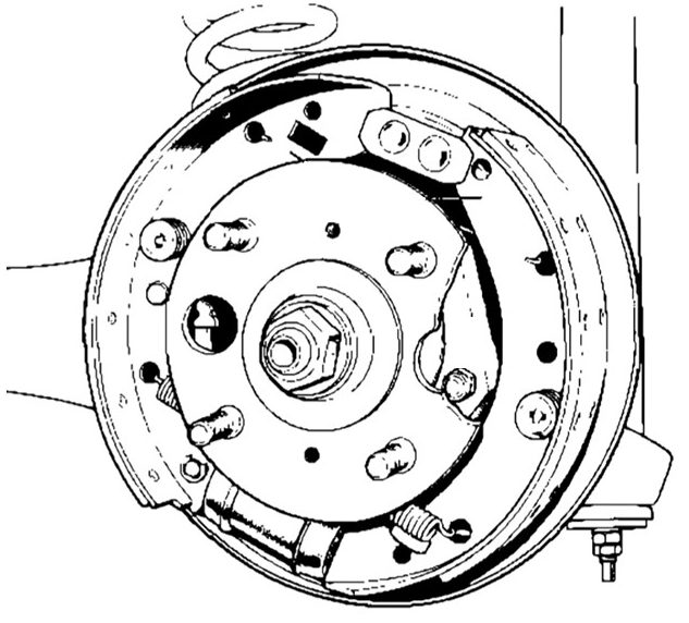
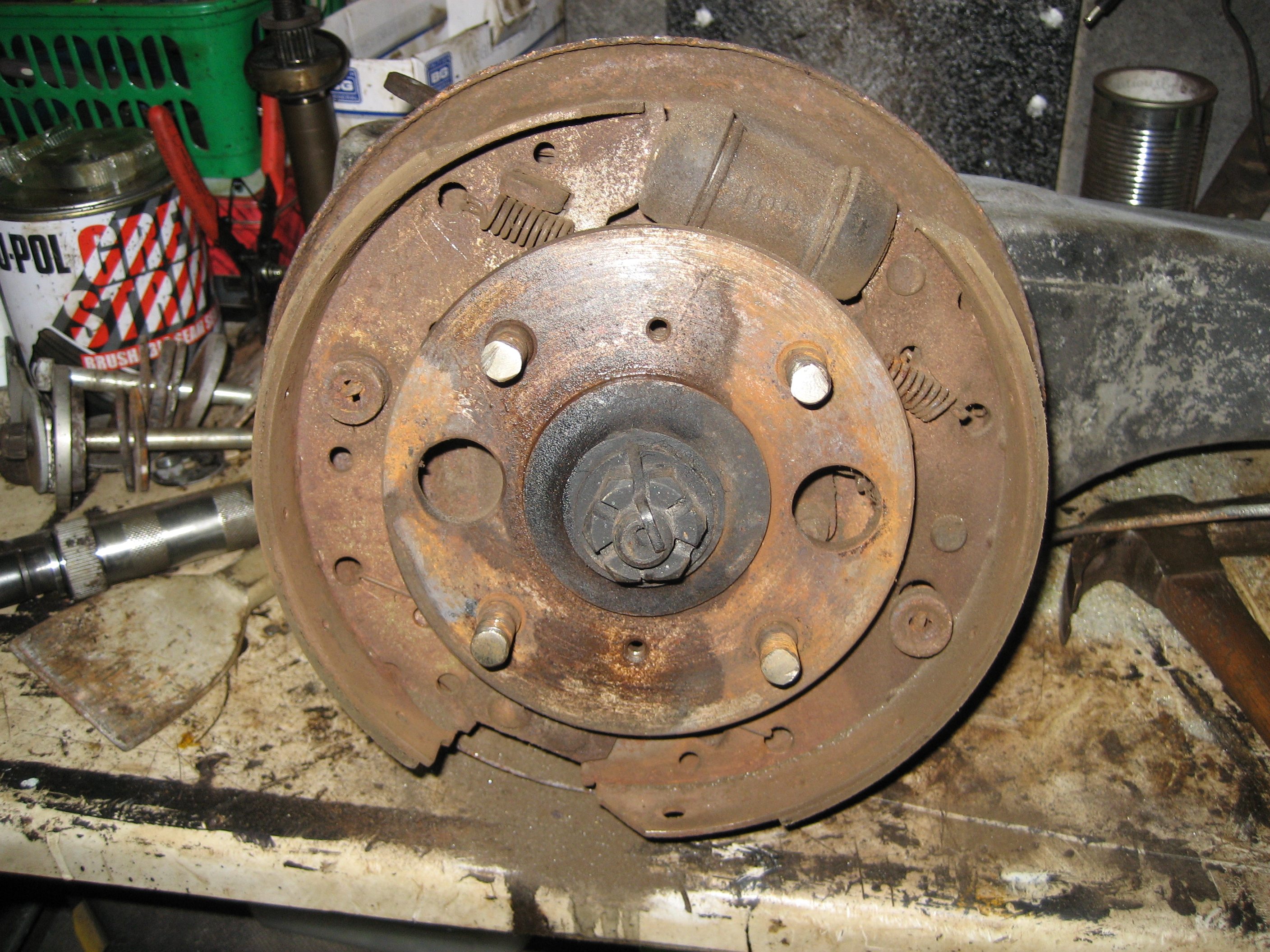
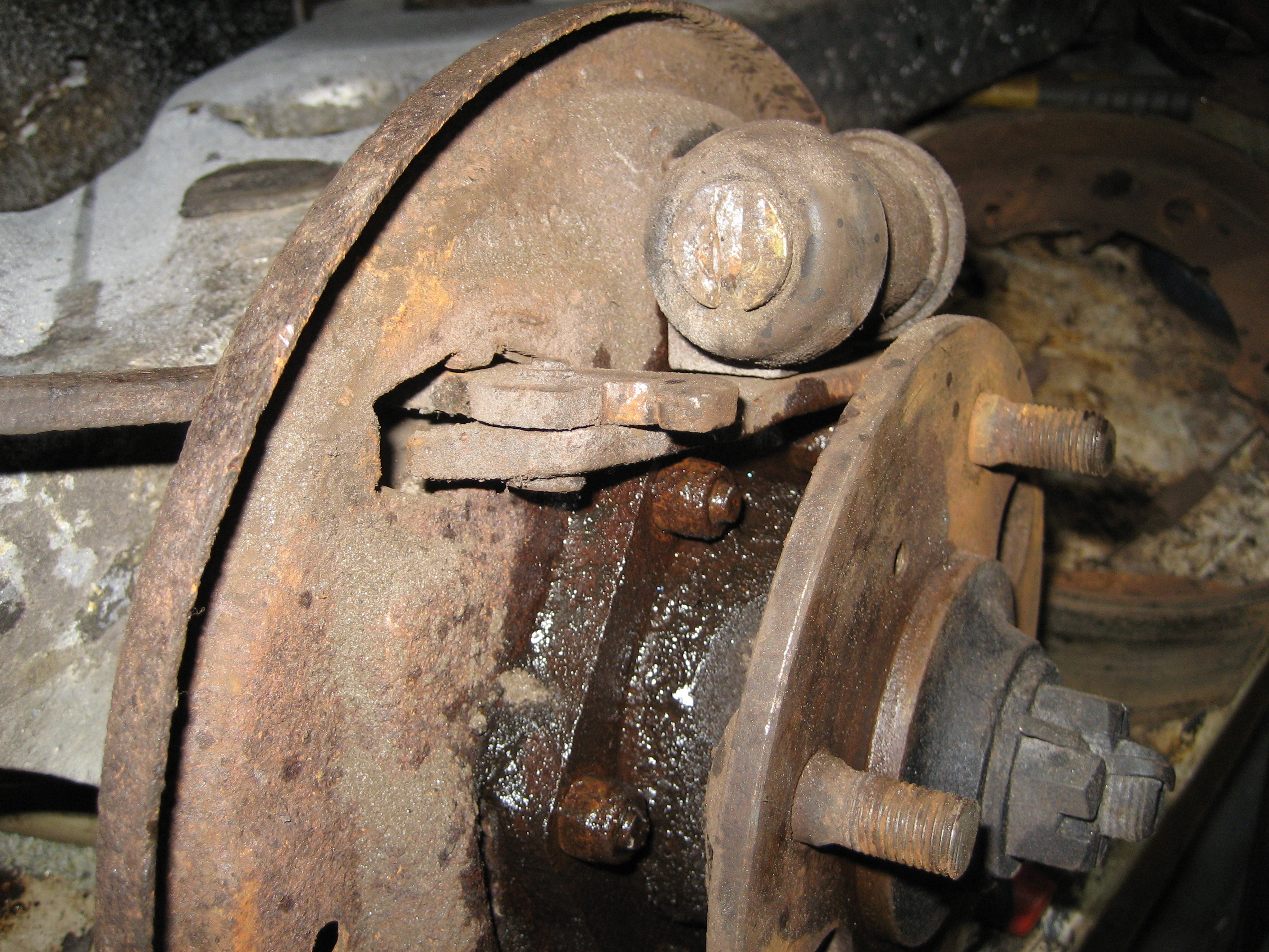
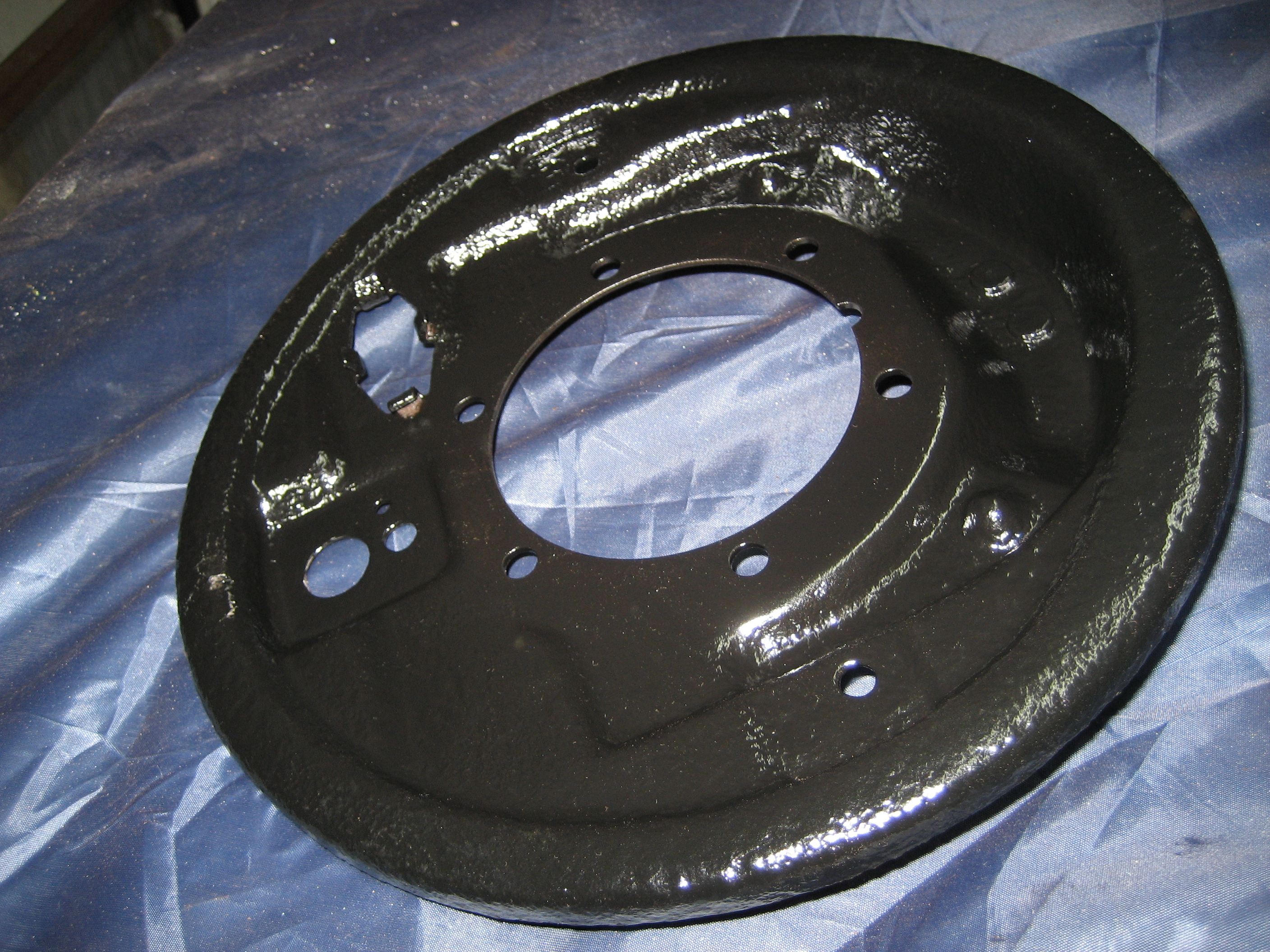
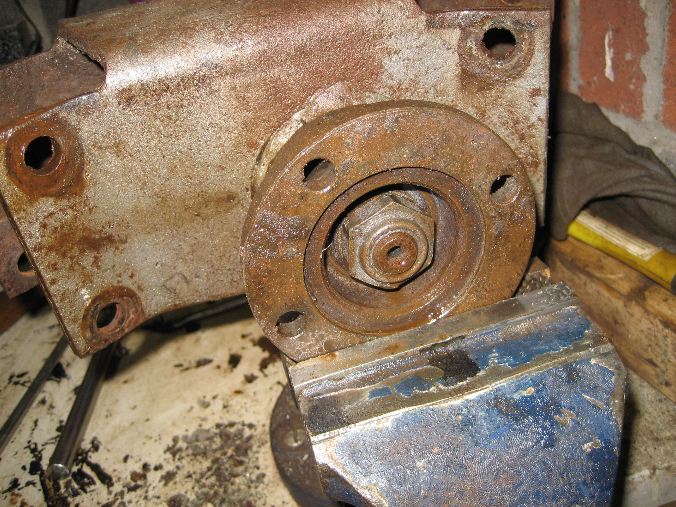
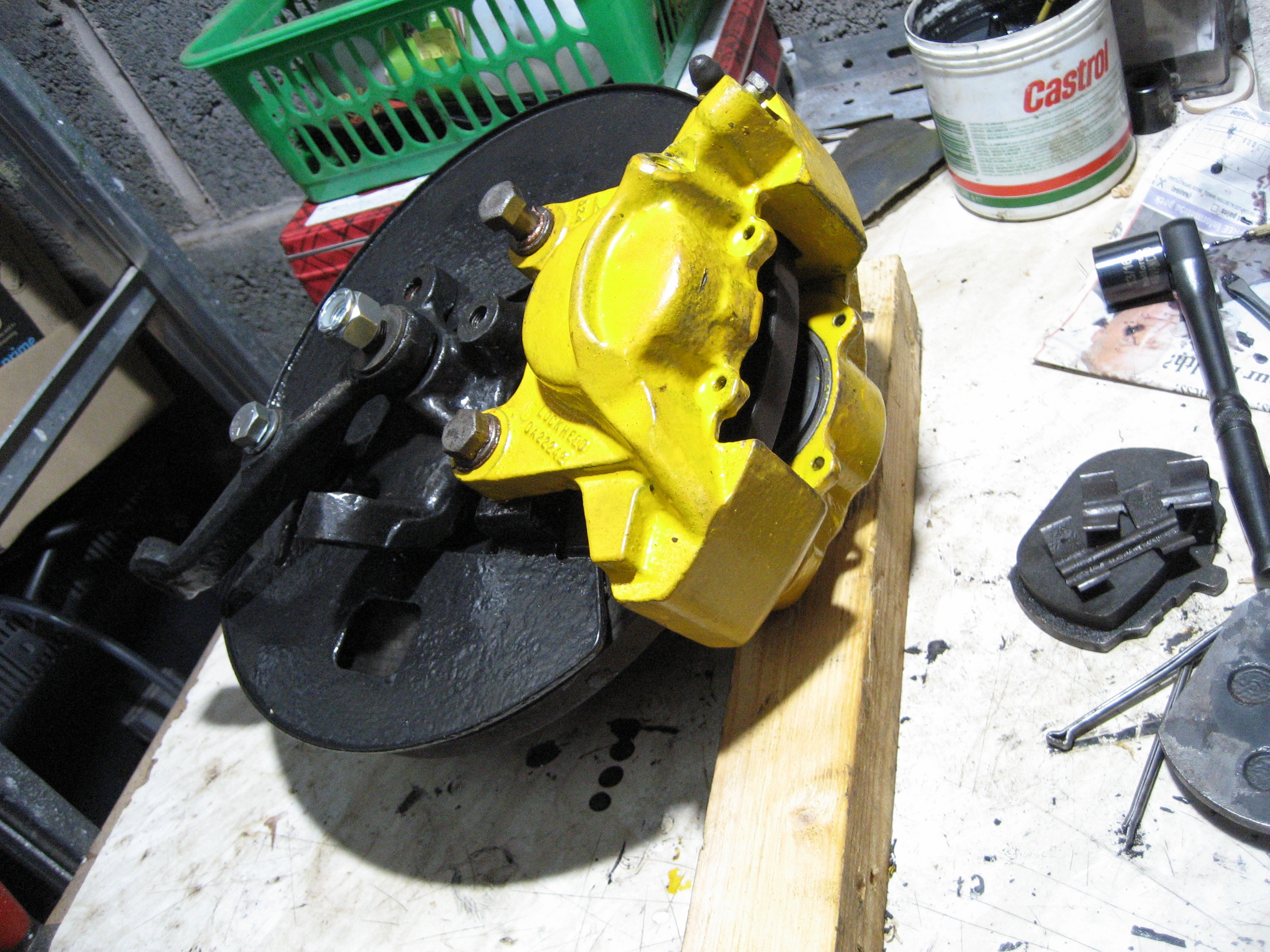
Hub and Calliper
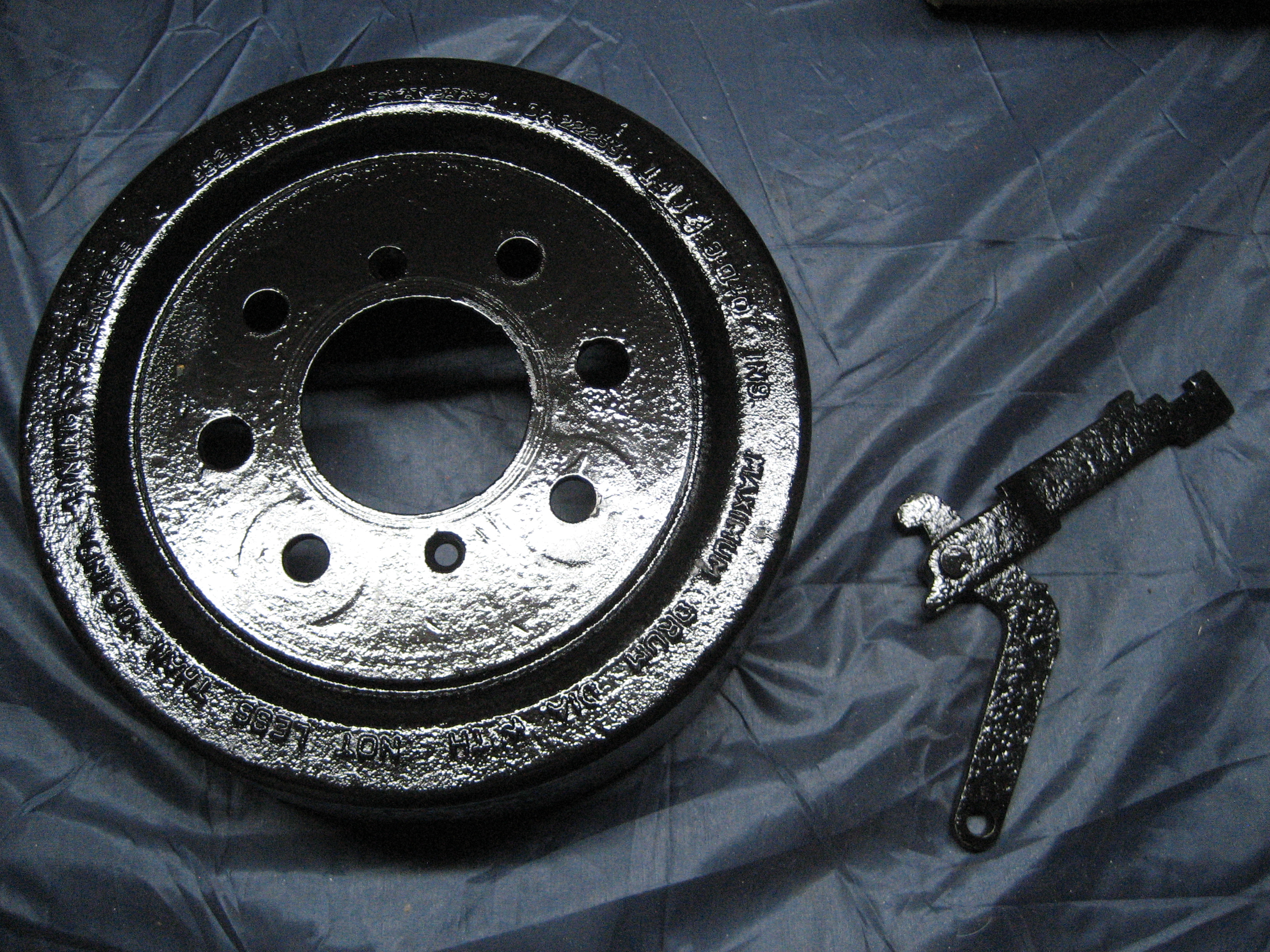
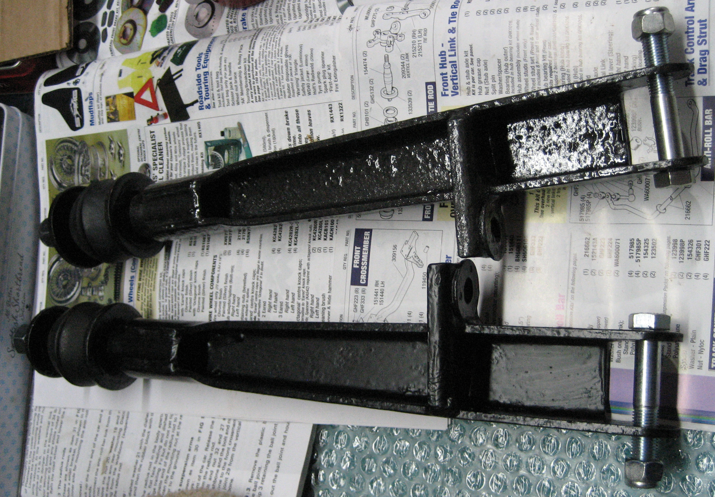
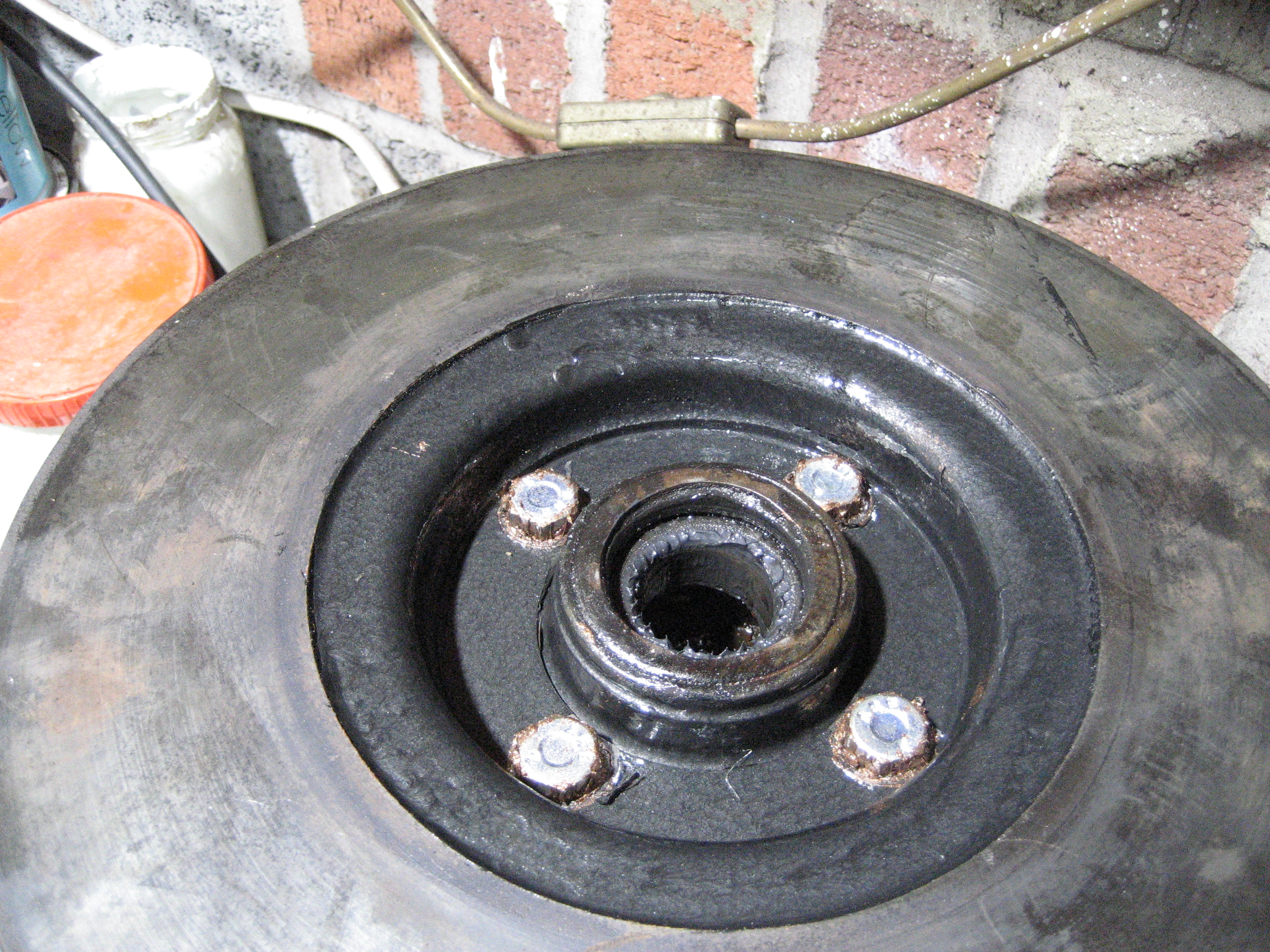
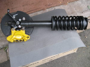
The most difficult peices to dissassemle turned out to be the easiest to reassemble. First I bolted the front hub assembly to the brake disk. The original bolts were seized solid, so I’ve made sure they have plenty of copper grease  on the threads before I put them together with new bolts.
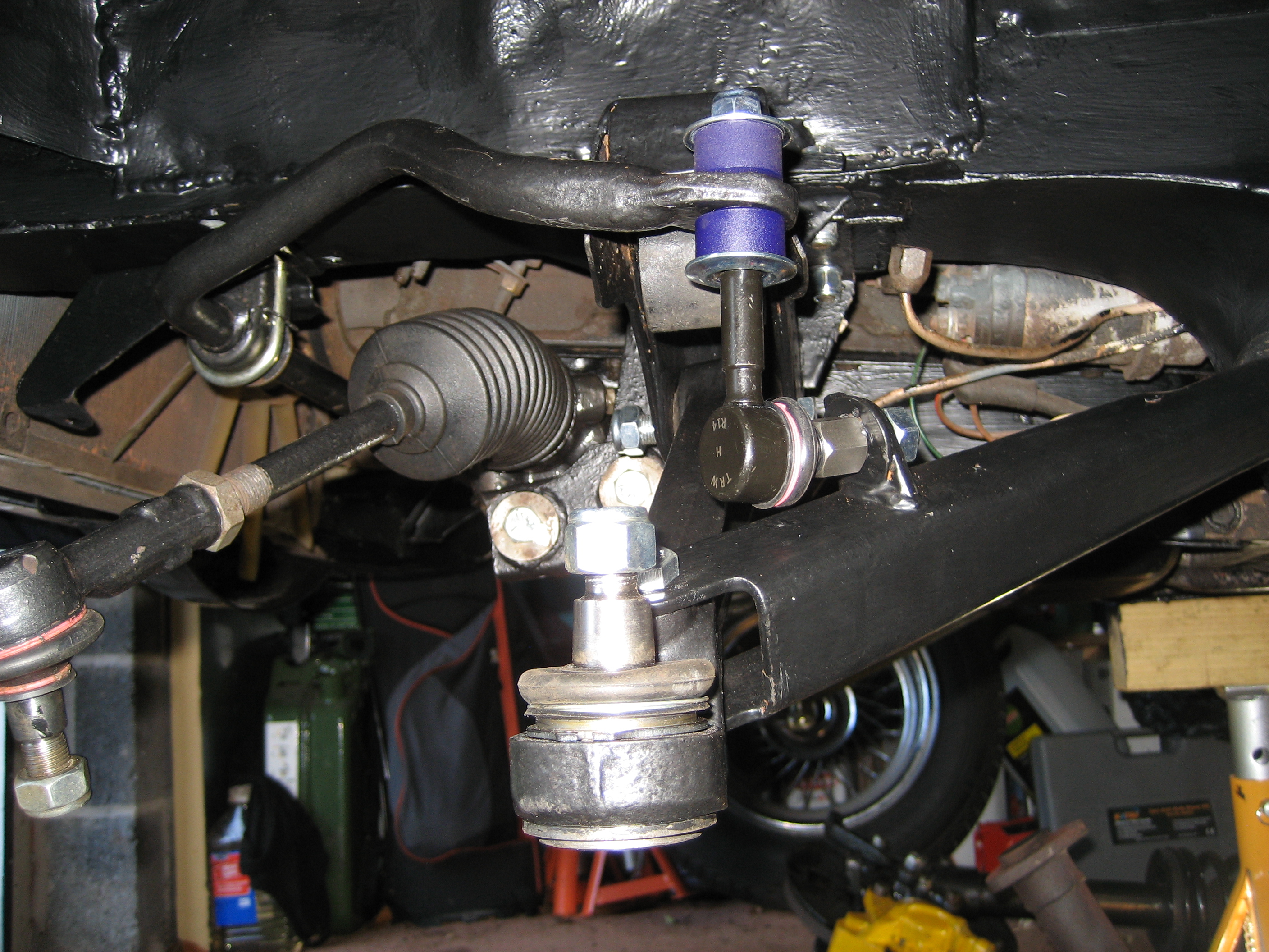
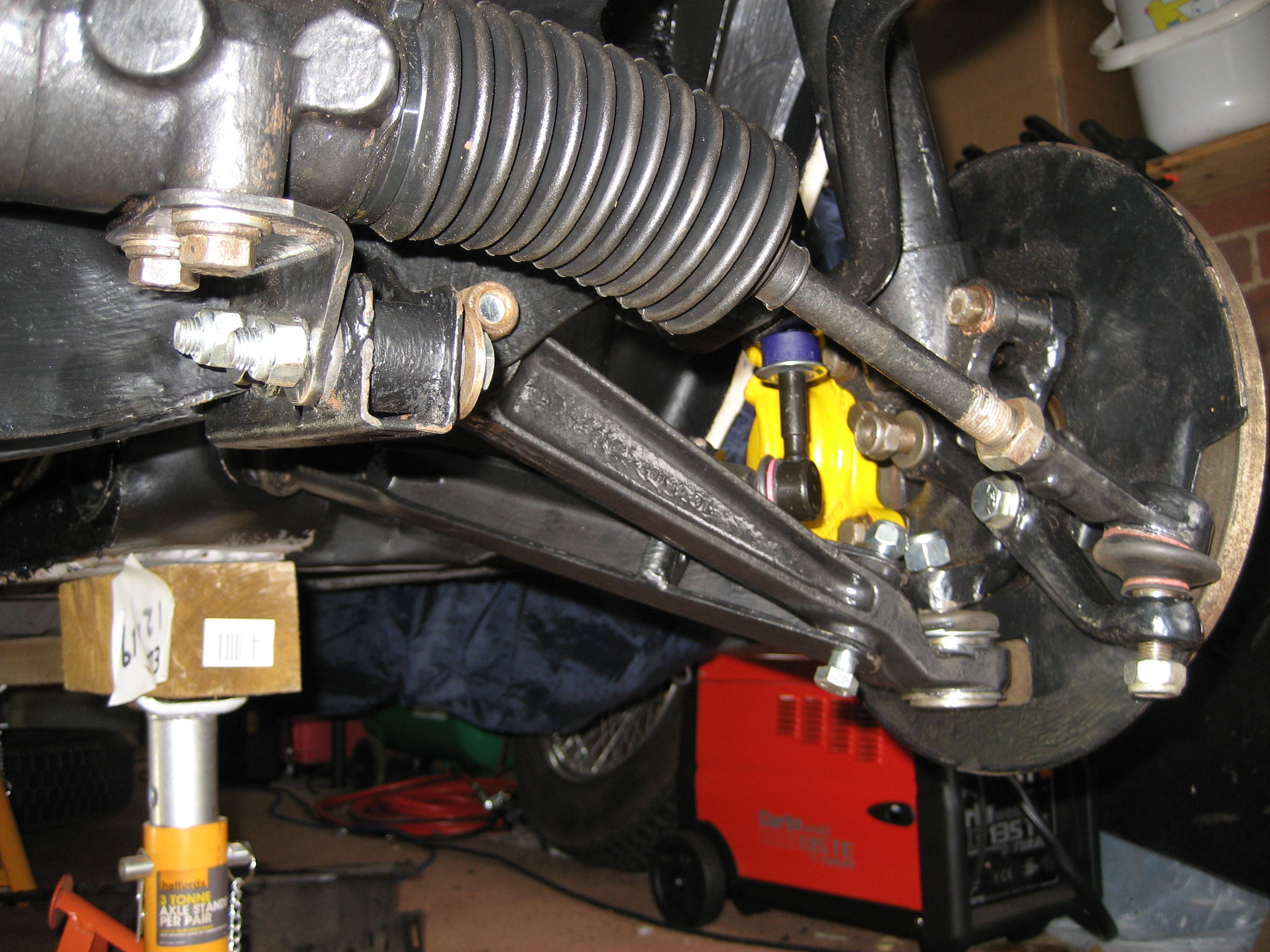
I then bolted the newly painted brake caliper back in place over the brake disk and re-positioned the brake pads – again with plenty of  copper grease on the back to prevent any squealing.
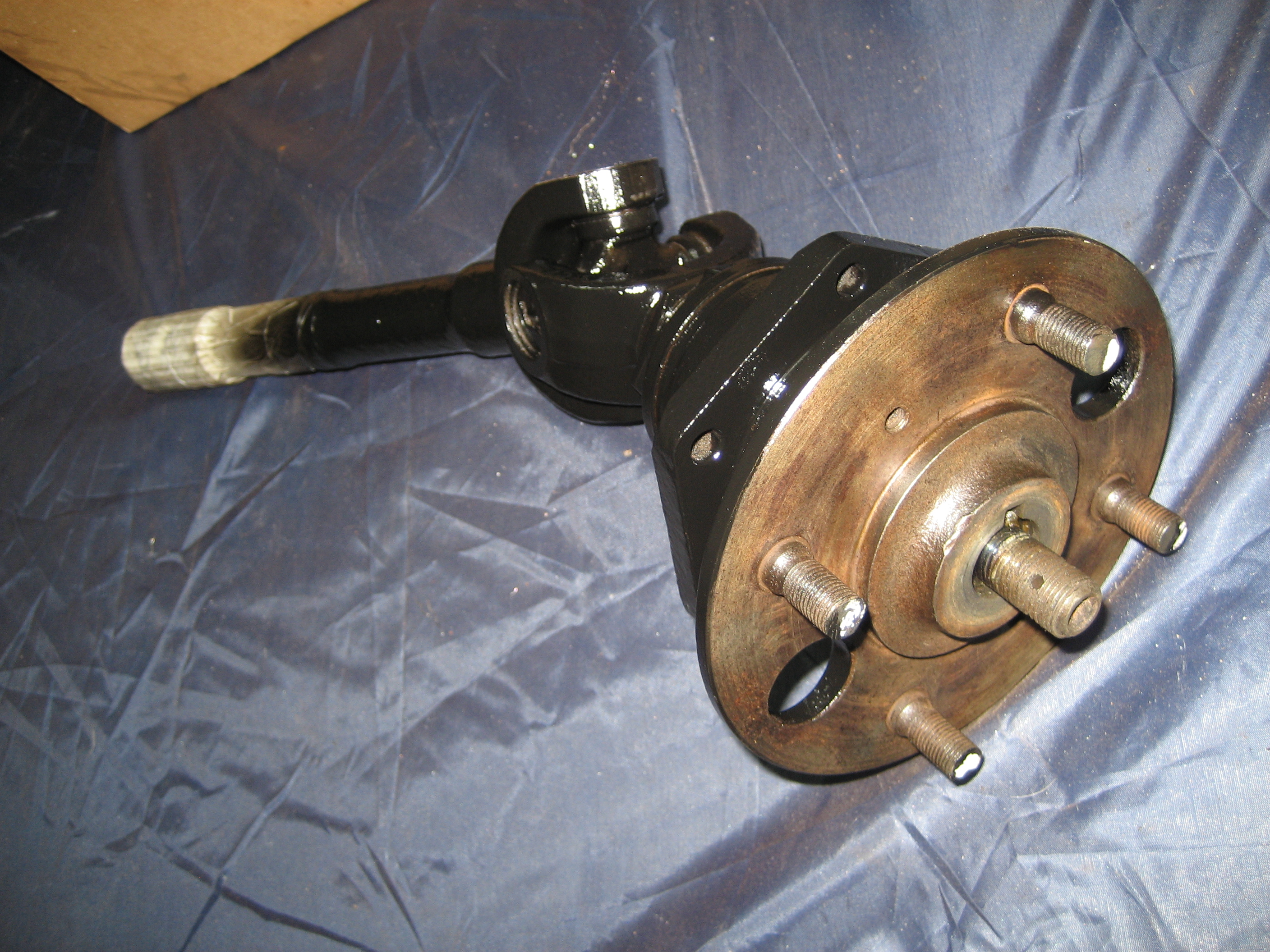
Finally, I bolted together the strut assembly and hub to complete the bulk of the refurbishment job. The full refurbishment job will be completed once the wheel arches are ready to accept them.
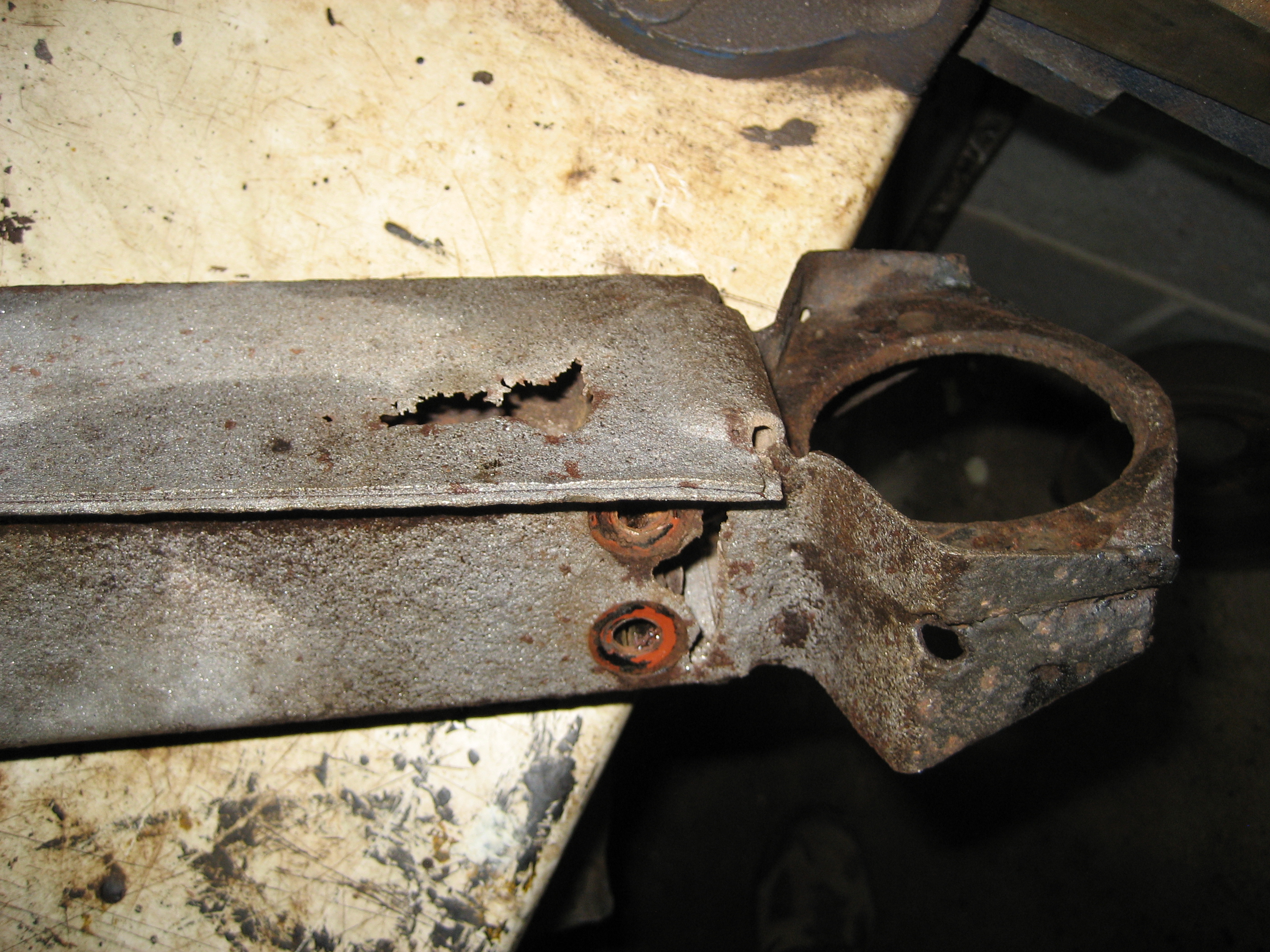
Addendum
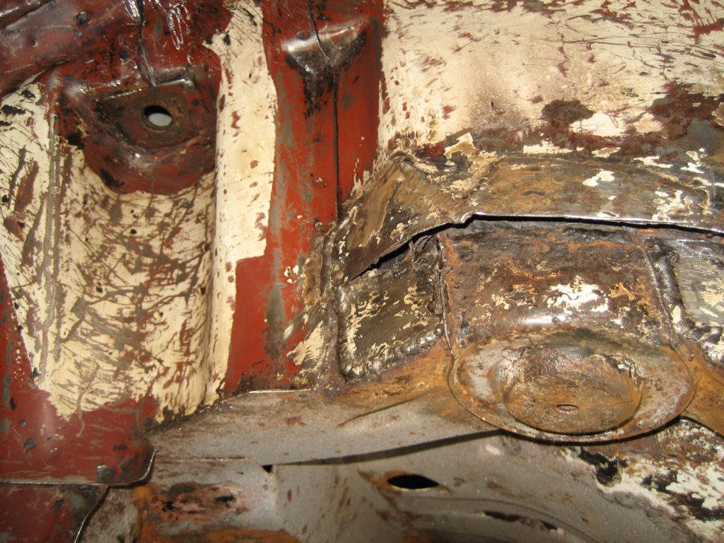
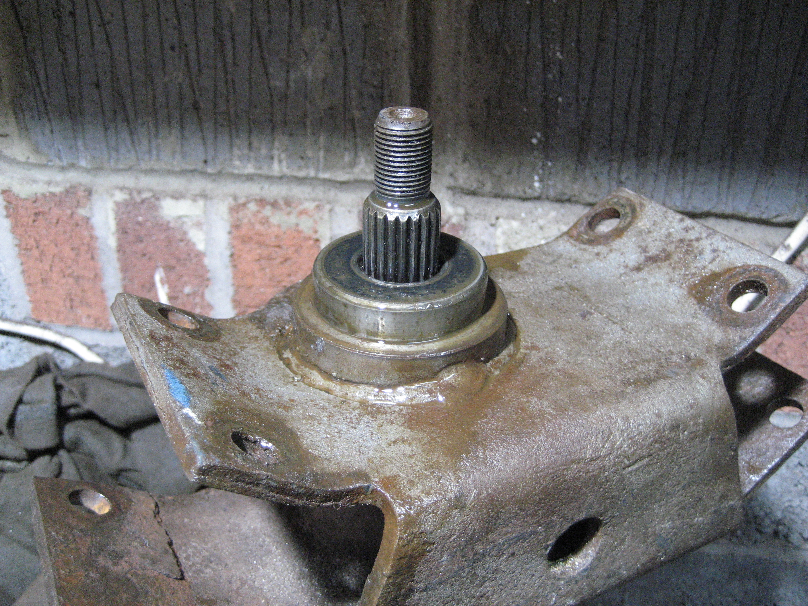
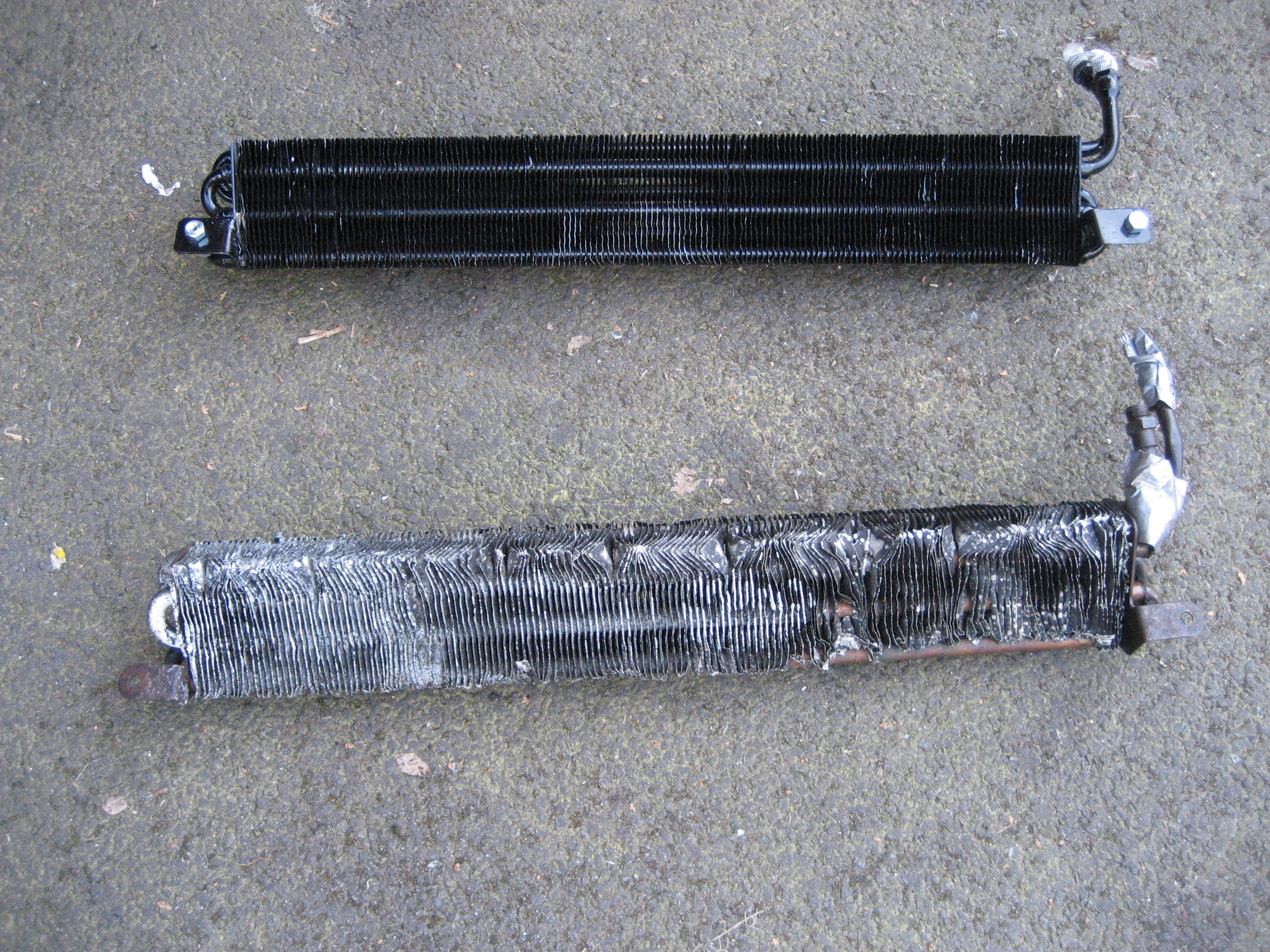
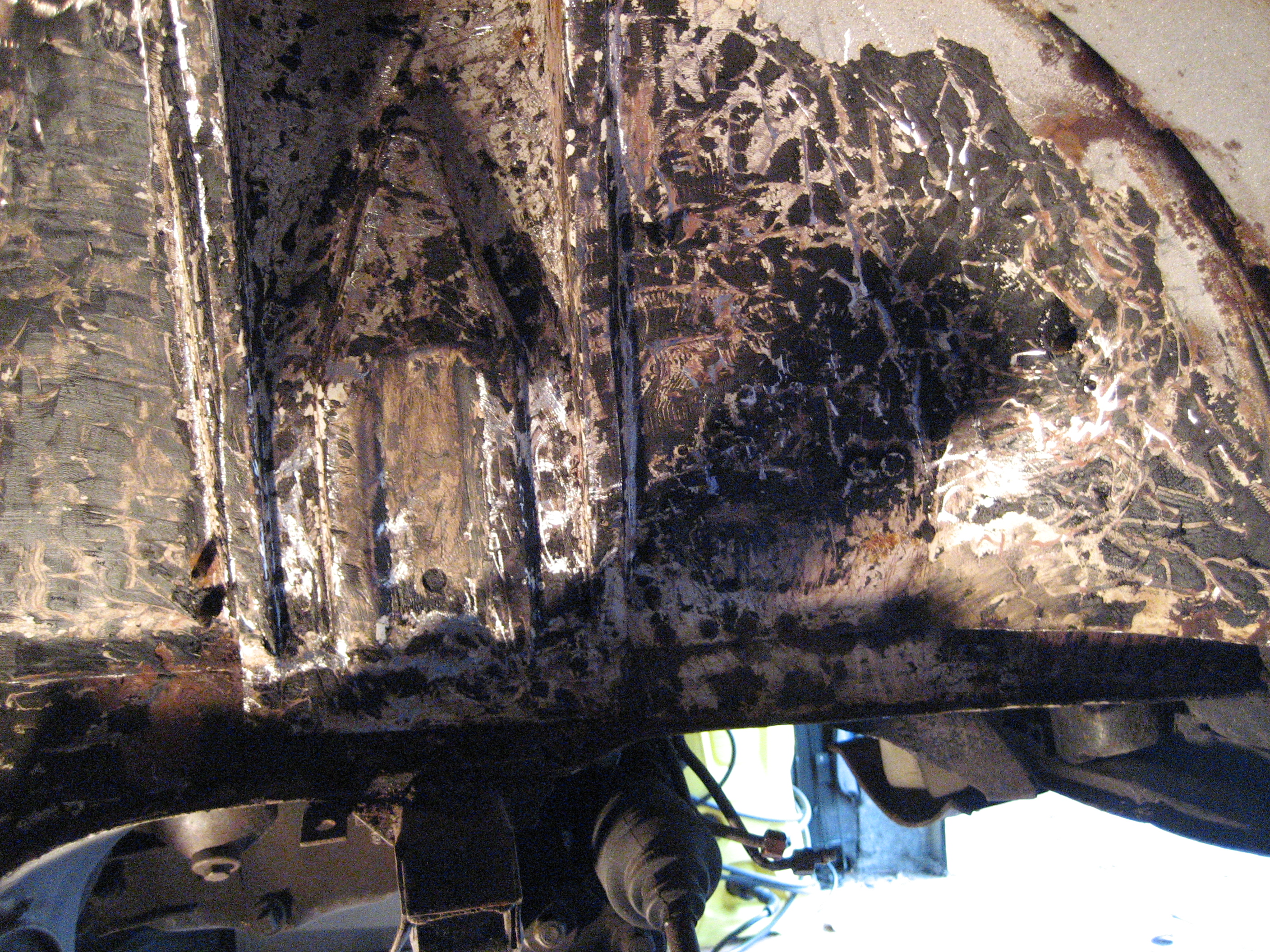
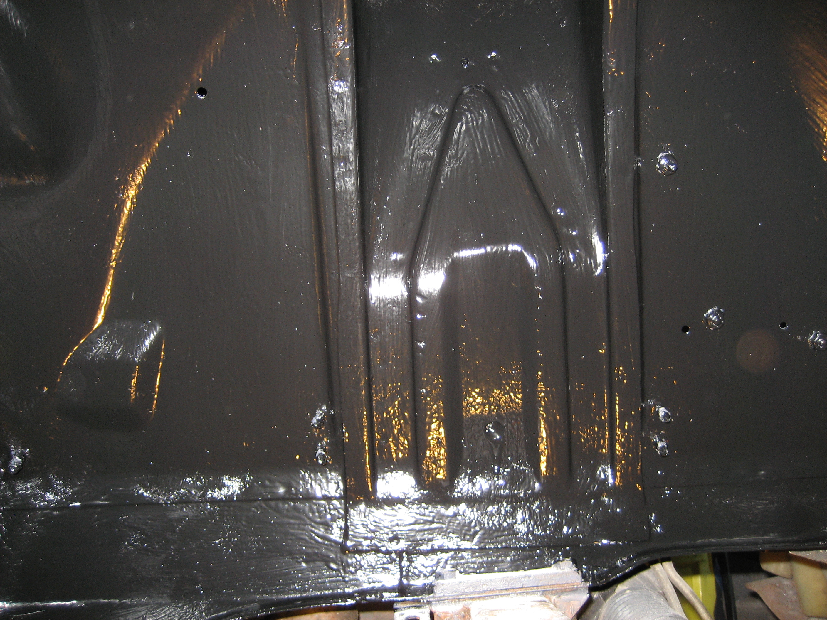
The next day I started the preparation of the front wheel arch ready to accept the nice reburbished suspension (see my next post). However, whilst my head was in the wheel arch as I scraped out the old underseal, I heard a loud noise. The strut insert and strut casing had parted company. All of that energy I so warily injected into the spring had ripped the threaded insert from the top of the strut casing. Luckily no damage was done, other than to the shelf that the assembly was resting on. It was removed from the wall by the rapid explosion of force released from the compressed spring.
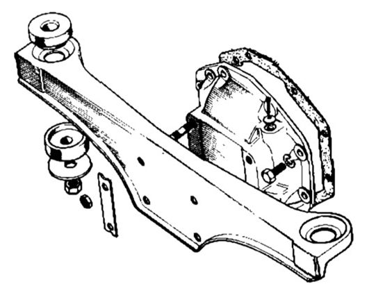
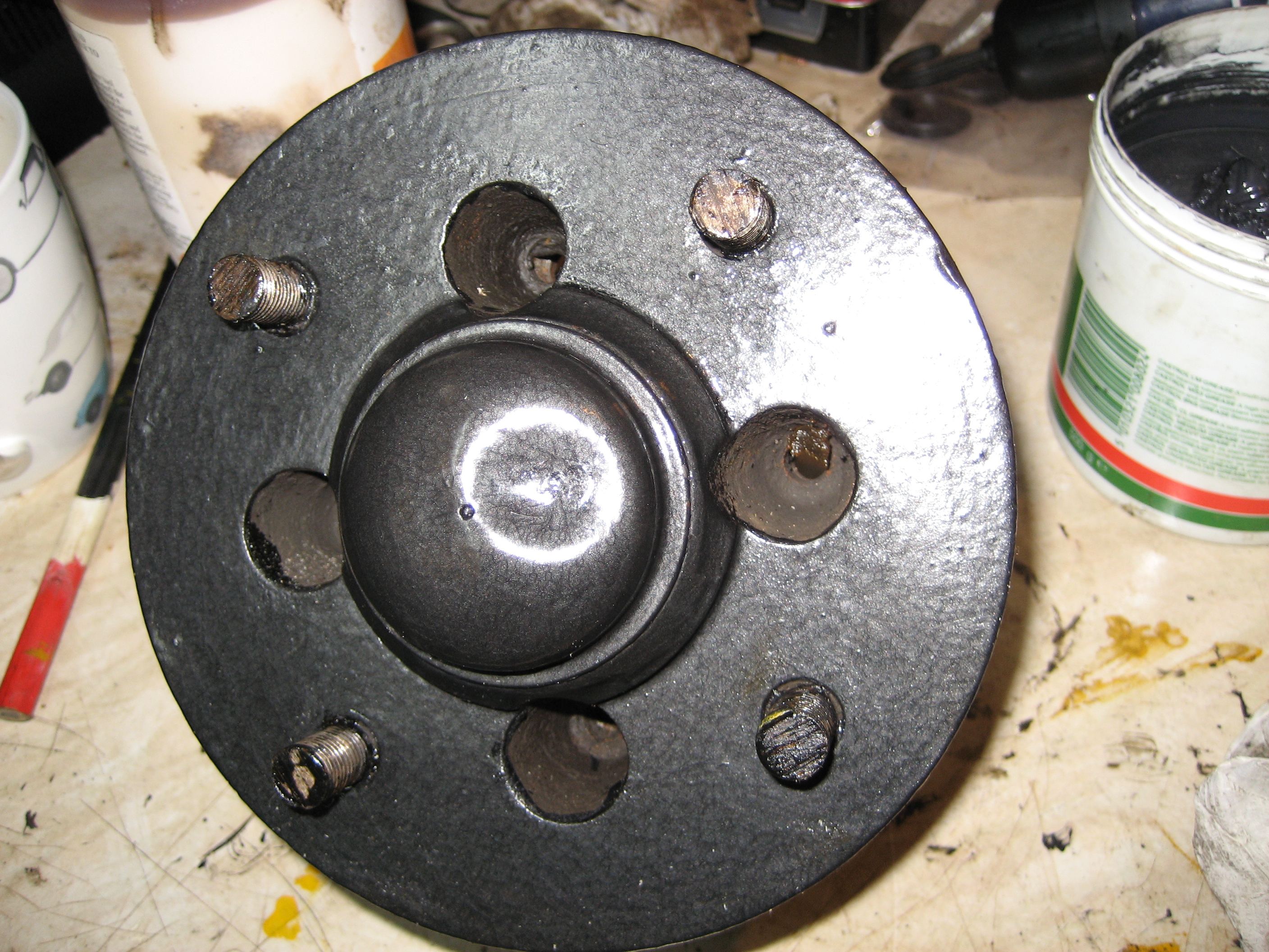
Note of Caution: Stag Suspension Refurbishment
I spoke with James Paddock to understand if I had bought the wrong damper and threaded strut insert. No – there is only one thread size. There are a few types of damper (Gaz, Koni etc.) which have slightly different profiles with slightly different shaped profiles of threaded strut insert, but they all have the same thread size.
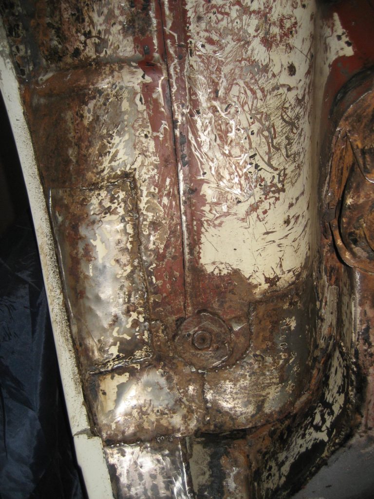
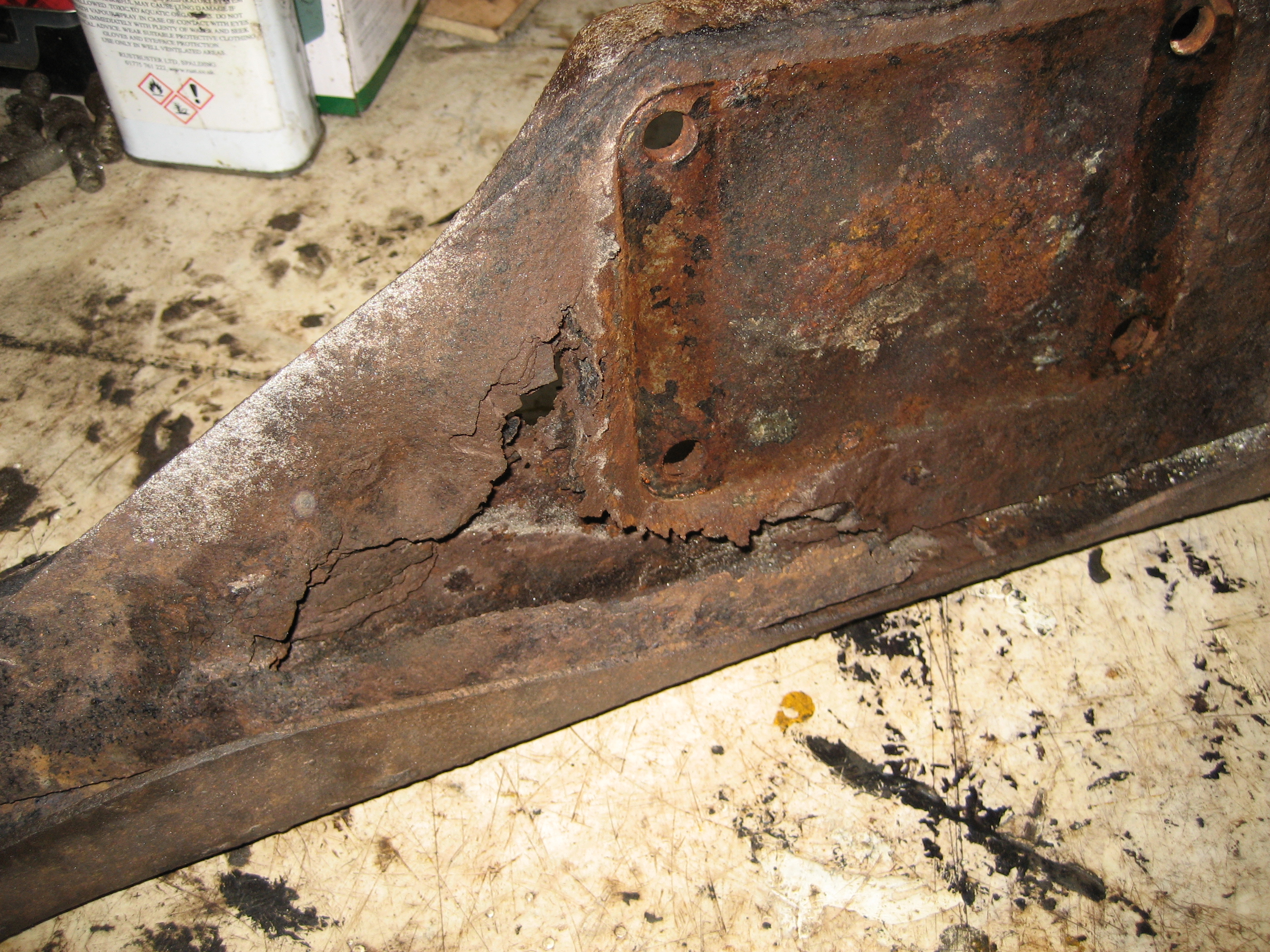
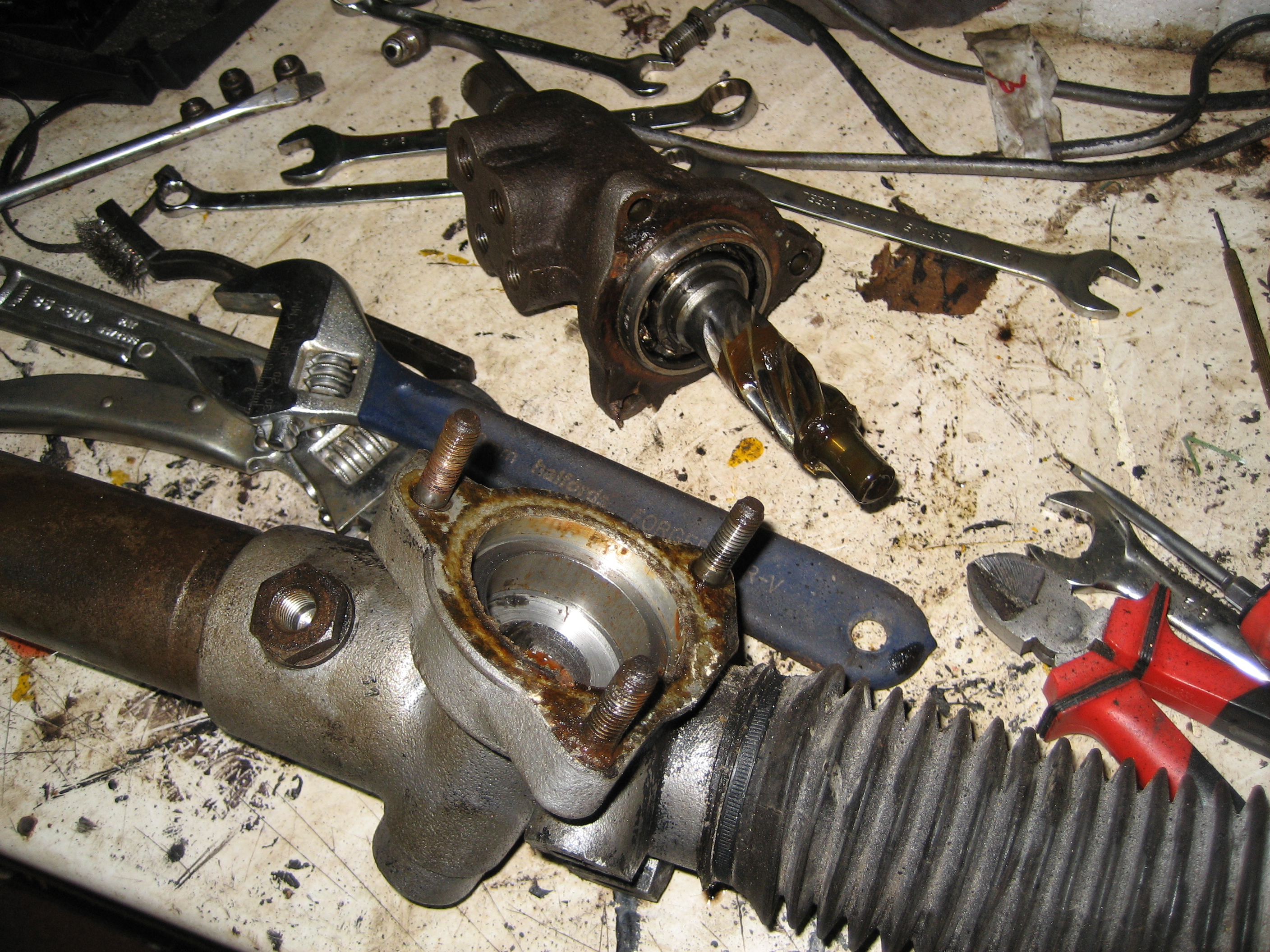
The most likely cause of the problem I experienced is the peening of the top edge of the strut casing which is put in place at manufacture. This process bends a small amout of the strut casing over the top of the threaded insert to prevent it coming free. This is the reason that the strut insert is so difficult to remove from the strut casing in most cases. In order to part the two, the peening must be reversed by re-bending the strut casing with a hammer and drift. This effectively opens up the diameter of the threaded part of the casing if not done very carefully. I am pretty sure this is what has happen, as I didn’t have any trouble parting the strut insert from the strut casing and the new threaded insert “dropped” into the casing a couple of millimeters before it engaged with the threads.
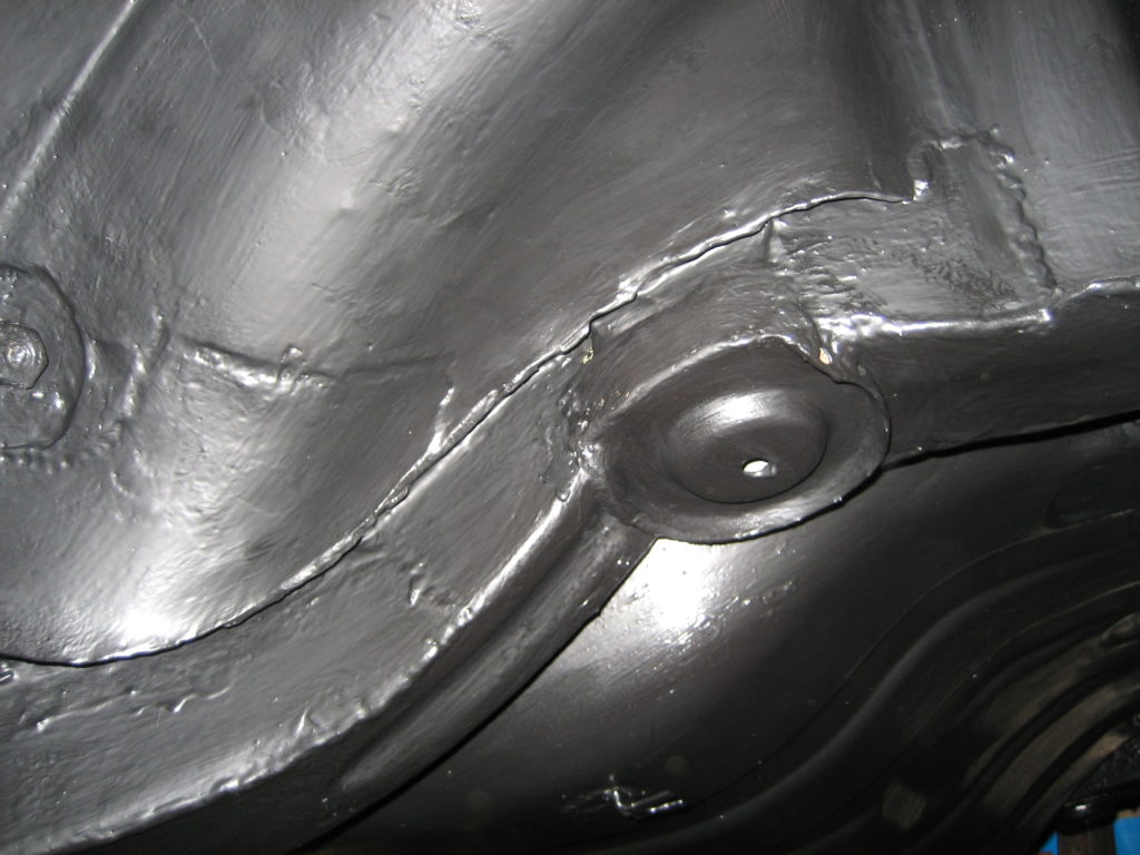
James Paddock put me in contact with Tony White (Stag breaker) who luckily had a spare couple of strut casings for sale. These both confirmed my hypothesis. The threaded inserts fitted far better into both of these units. No clearence, no “dropping” in and much tighter. I will scrap the originals and use these once I have cleaned and painted them.
This could have ended far worse had I been in the vacinity of the strut when the two parted company, or even if this occured whilst driving. Pay special attention here!!