Manufactured in 1973 with commission number LD23036 BW, (BW standing for Borg Warner 35 – the model of the auto gearbox), with Body Colour 19 (White) and Interior Trim code 11 (Black).
The mileage on the current MOT shows 65,730.
The car has done roughly 500 miles in the last 27 years!!
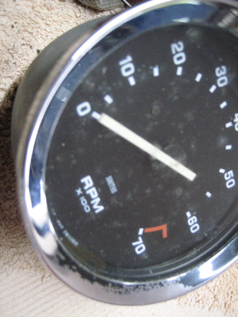
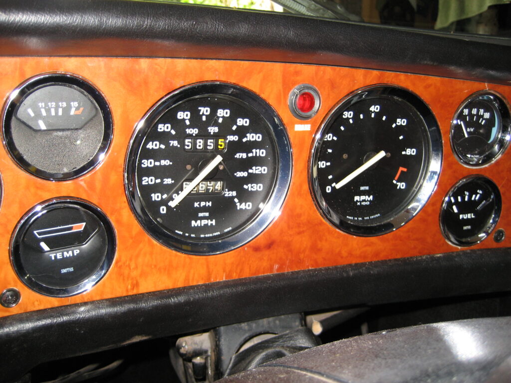
After almost 50 years, most of this time spent in musty damp garages, the dials and gauges are looking their age. On the inside of the glass there is dirt and perhaps even mould.
I researched if it was possible to clean these without sending them to a profession refurbishing company. I decided that a simple cosmetic refresh was well within my abilities.
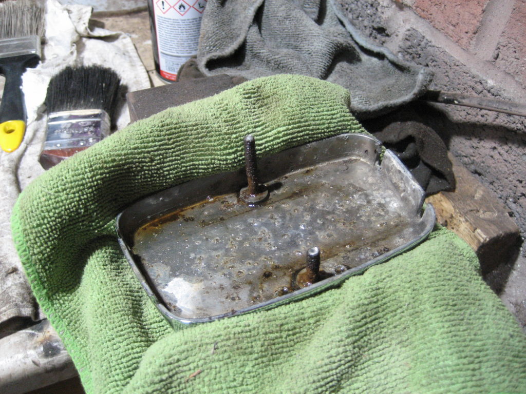
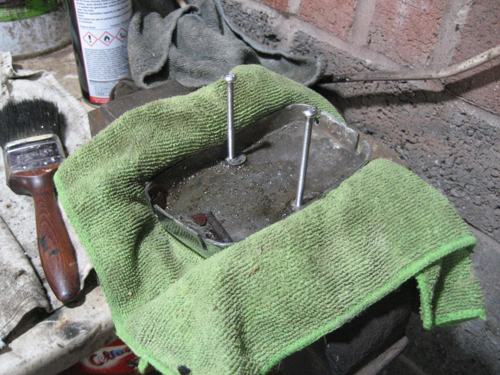
The chrome bessels are attached via folded metal tabs on the rear of the bezel and a layer of sealant that runs the circumference of the unit. Carefully bending back the tabs and then easing the bezel away from the casing is all that is required to detach the bezel and glass from the front of the unit.
The original sealant around the circumference had long since hardened / crystalised which is why the inner glass has probably end up the way it has.
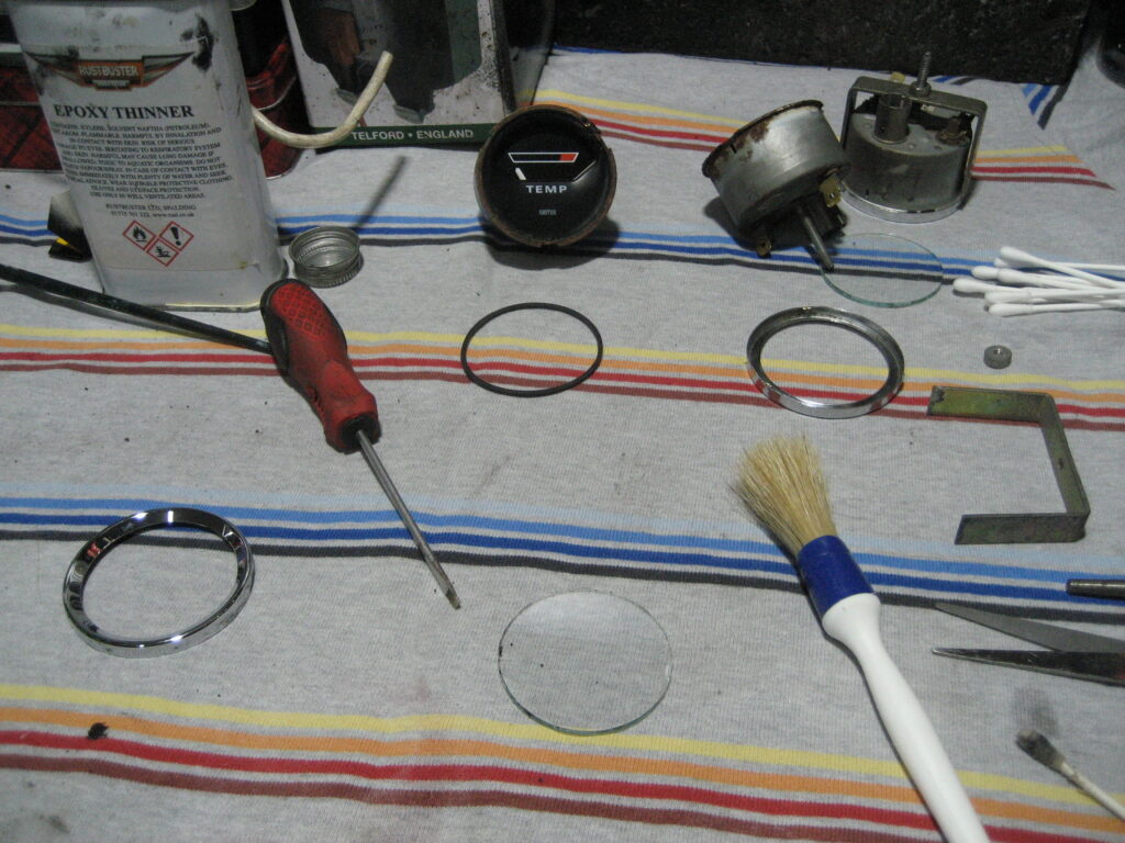
With the bezel and glass seperated from the unit, I cleaned the glass thoroughly with good old windolene. I then decided that the matt black coating on the inner surface of the chrome bezels was too scratched and chipped to look as I wanted. Some strong solvent and a cotton bud dissolved this without harming the chrome underneath.
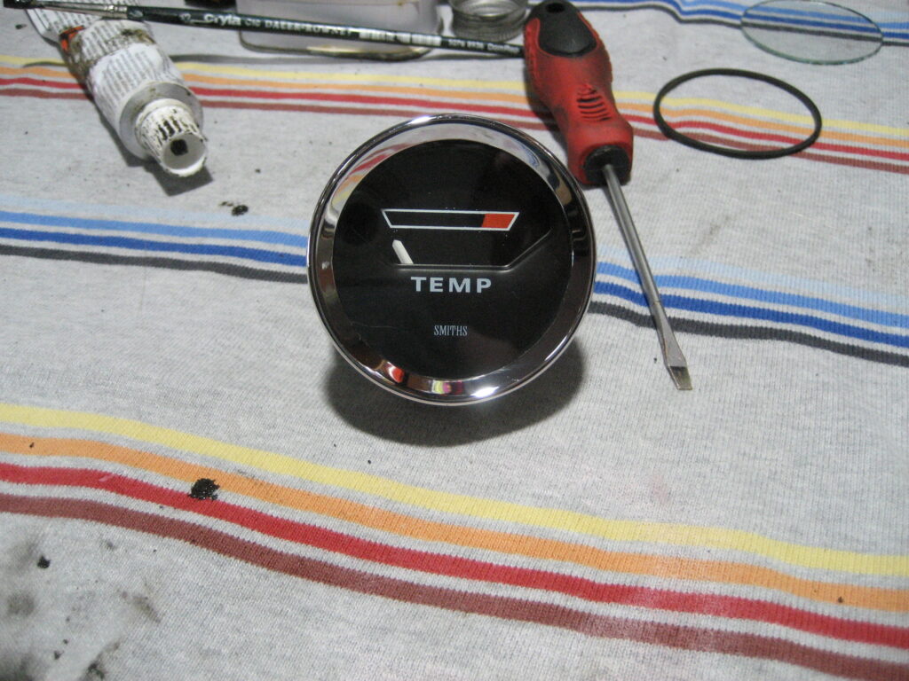
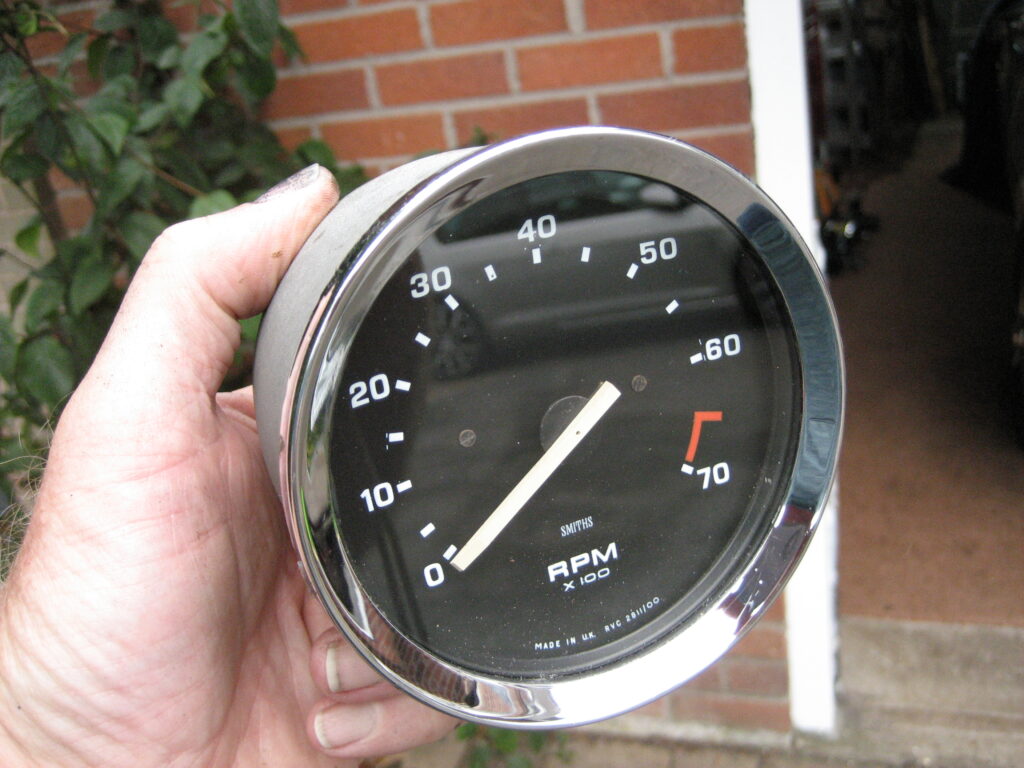
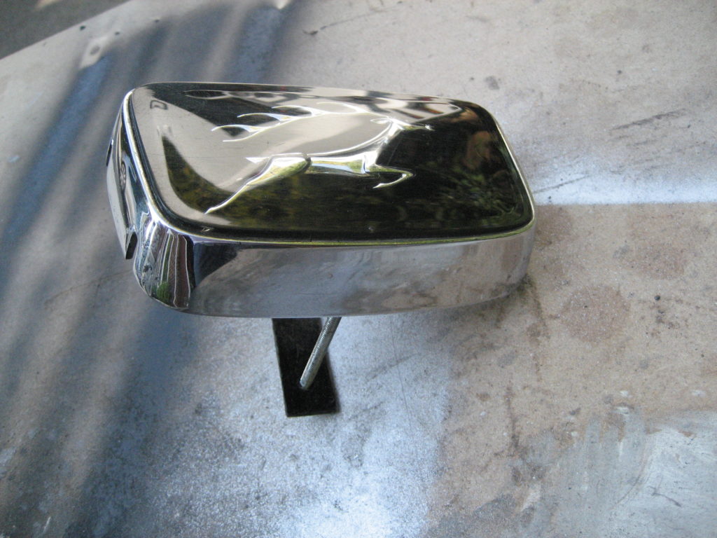
Once I was happy with the bezel and glass, I reassembled using some gasket sealent to re-seal the circumference of the gauge. I started with the Temp gauge (as I had a spare), but as the process went well I moved on to the Rev counter and was rewarded with a similar positive result.
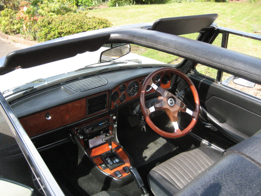
It takes some time, and is a little fiddly, but the results speak for themselves. Here’s a picture of the dash now that all the dials have been cleaned
OOPS…….
The next day after cleaning the dials I took the Stag out for a drive as the sun was out (any excuse). The fuel gauge was reading higher than I remembered and the Temp gauge just kept on climbing. The fuel gauge over reading I simple put down to connecting it back incorrectly. But the Temp gauge started off as it should – in the cold area. As I drove it moved to the half way point as it normally does, but then it kept climbing. I managed to get back home as it approached the red.
Opening the bonnet, I checked the water flow. The top of the radiator was hot as expected. So was the expansion tank. No leaks. Plenty of coolant. Bottom of the radiator cooler than the top. Nothing seemed amiss.
Then my slow brain put the two items together. The Temp gauge and Fuel gauge both use a 10v feed from the voltage regulator which mounted behind the speedo. This regulator is a 1960’s regulator. It operates using resistance wire, a bi-metallic strip and heat. I think that I may have distrurbed it whilst cleaning the guages and the thermal fatigue of almost 50 years use as cuased it’s demise.
Since the Stag was designed, there are now solid state equivalents of the 10v voltage regulator that are more stable, accurate and cheaper than the original.
You can’t tell from the photo, but this replacement is actually smaller than the original and is an straight forward replacement. The guages now read as expected – not an over-heating problem afterall – phew – I was worried as I drove home with the needle climbing.
Although not a problem for the MOT, my local garage did advise that I may want to consider new rubber. Looking at all 4 tyres, only one has a DOT code. The DOT code on that tyre dates it to 1995, 1985 or 1975. The others (all matching Michenin) don’t have a code which has been mandated since 2000. The conclusion is that all 4 tyres are more than 20 years old and possibly closer to 30.
There are numerous horror stories about tyre failure of older tyres at speed, especially on motorways, so I decided to replace them.
The original factory fit tyres were 185/80 R14 which have a rolling circumference of 2047mm. You can’t buy these from a standard tyre shop, only as specialised vintage tyres. Yes some would say that you need to keep the car original. I am a little more pragmatic. I prefer modern tyres in current standard sizes, so they can be easily replaced if required, at any tyre shop, and at reasonal cost.
As the car is now running on 15″ chrome wire wheels, I went for 195/65 R15. A little more rubber on the road and a rolling circumference of 1994mm. This is a variance of 1.67%. which is well within tolerence of the speedo.
Now the local garage is open again, it was time to test the quality of my work over the last 2 years on this project – MOT day.
She passed with no advisories – I am really satisfied with the result so far. So far, because there are a lot of cosmetics to finish. But she is now drivable for the summer.
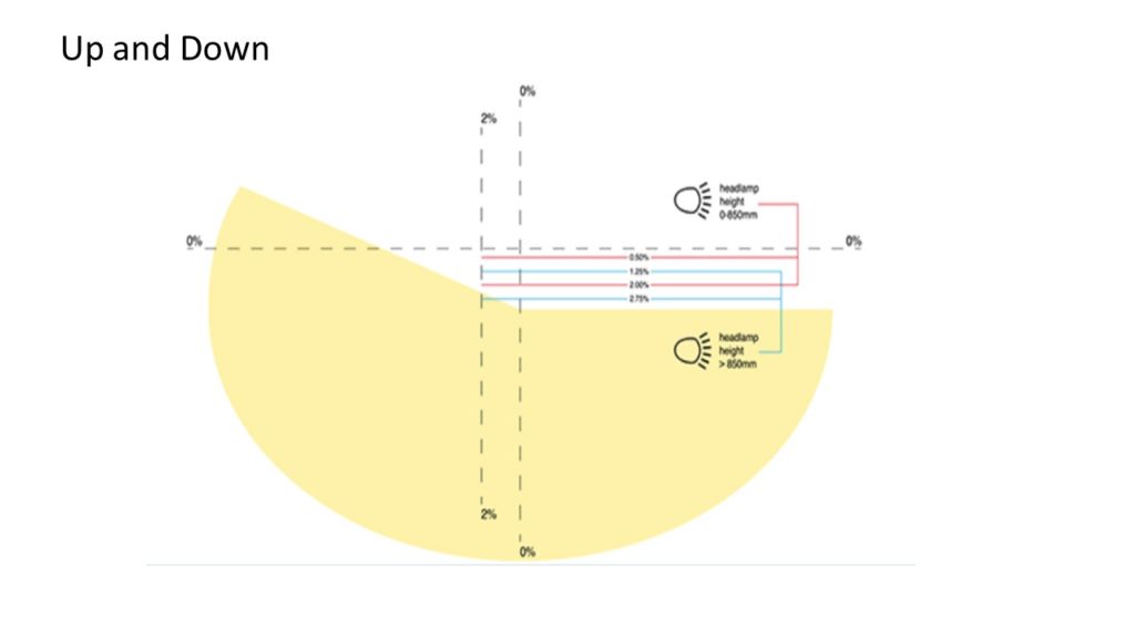
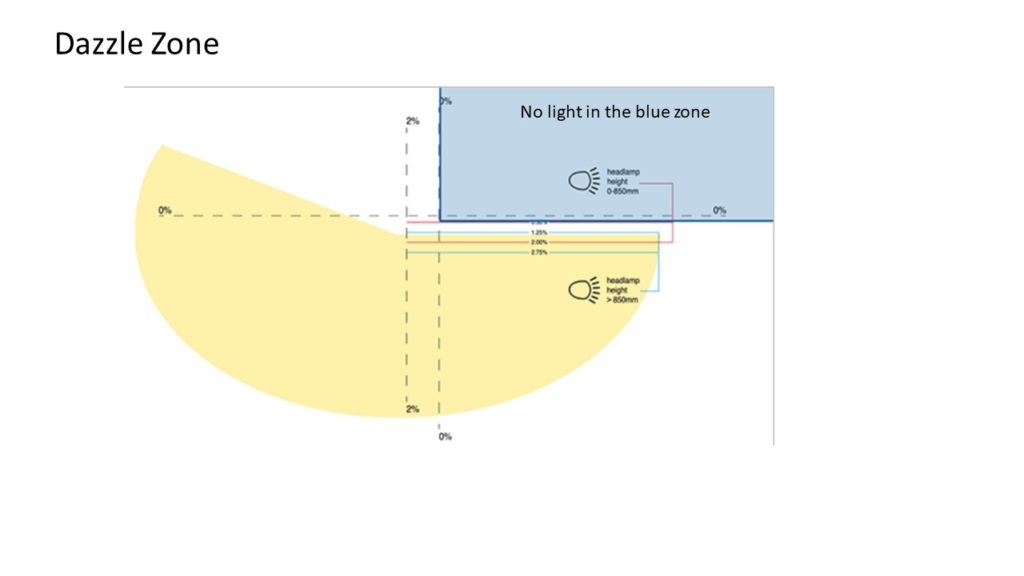
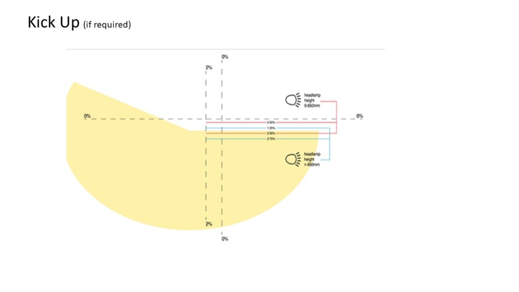
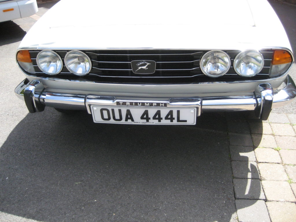
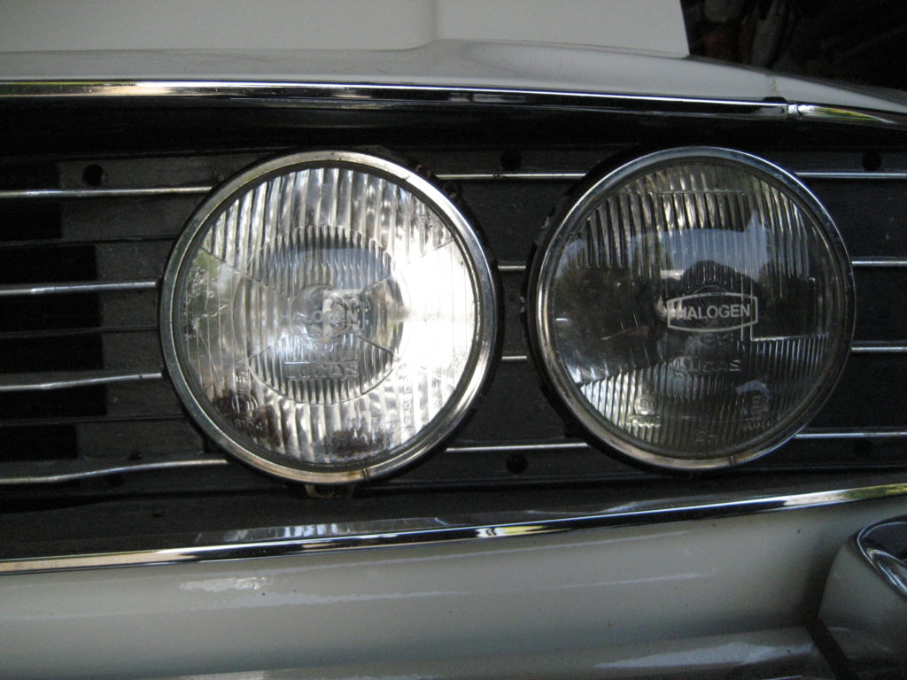
The current DVLA rules on headlight alignment are covered in the 3 pictures below. In practice you need to park up 3m from a flat vertical surface:
Main beam needs to be directed straight and level
Dip beam need to drop to 2″-4″ below level and slightly left to avoid dazzle
If your headlights have a kick-up then that need adjusting too (mine didn’t)
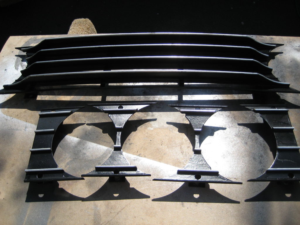
When using standard Stag headlight adjusters, it’s the adjuster at 1 O’clock for height and the adjuster at 7 O’clock for direction. Here the finished lights and grill
Once I have adjusted the headlights and replaced the front grill, it will be time for MOT. As it’s older than 40 years, it doesn’t necessarily need one, but I have done some extensive restoration work and want to make sure all is well. With the Covid lock-down still in place, my local garage is closed, and I can’t go out driving anyway, so I guess i’ll have to wait.
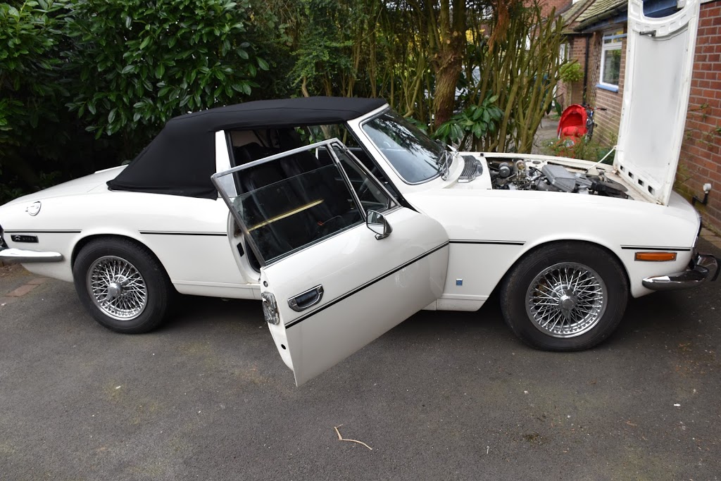
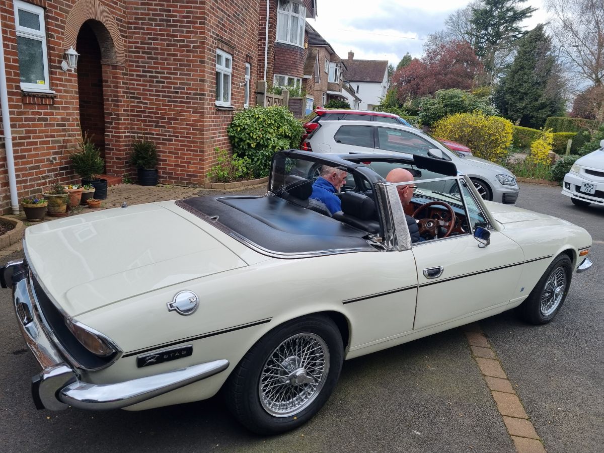
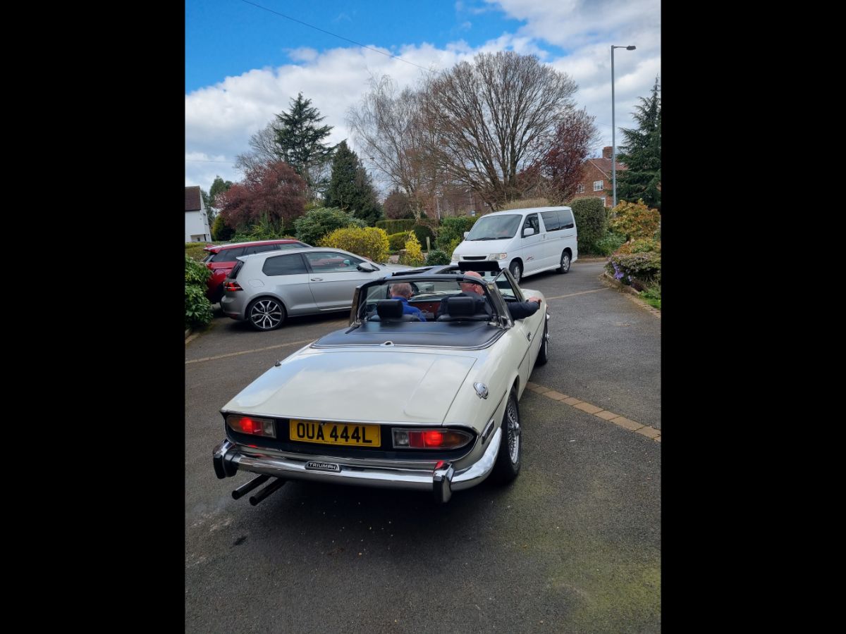
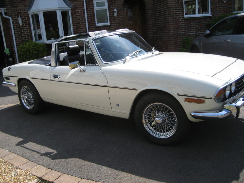
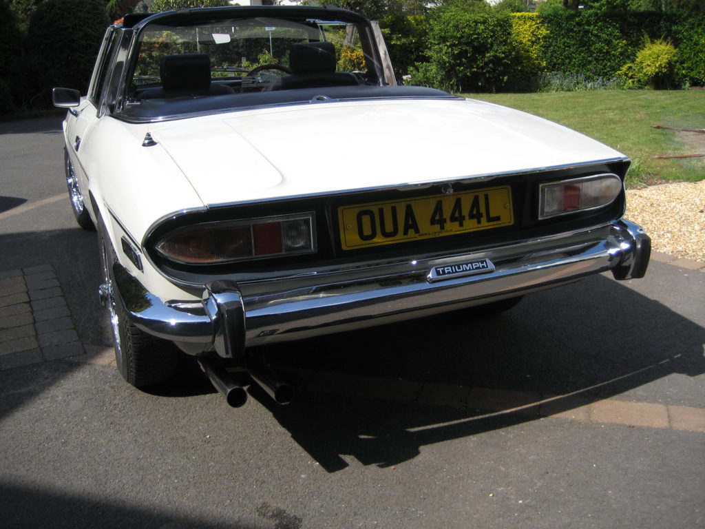
Here are a few pictures of the car as it now looks.
This is an almost 50 year old vehicle, so I am not expecting perfect chrome, especially since this car has been used during it’s long life, unlike some which seem to have spent their days in a dry garage.
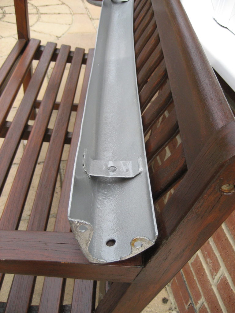
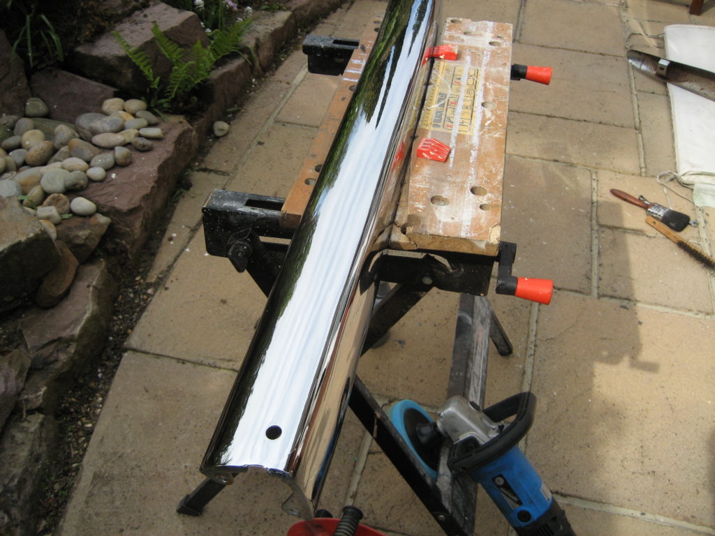
After removing the front and back bumpers, over-riders and mounting brackets, I took them outside into the sunshine along with my polisher. The bumper brackets were not in bad shape, having been galvanised. Just a quick wire brush and a coat of hammerite. The front bumper has fairly widespread micro blistering across the whole of the bumper and rust building up on the inner side. So a wire brush and silver hammerite were applied to the inner surface, and large amounts of metal polish and the elctrical polisher to the outer.
The results were pretty good – although not perfect. The chrome responded very well to the polish, coming up really bright, but the micro blistering is still noticeable if you look closely. As a new chrome front bumper is over a grand from Rimmer’s, I can live with some minor imperfections. This is not and never will be a concourse car.
The centre peice of the rear bumper was in very similar condition to the front, but the corner sections were a little worst. The chrome had blistered through in a couple of places. As with the other bumper sections, I can live with the imperfections at the current time, but will keep an eye out for second hand corner sections in better condition.
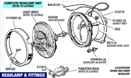
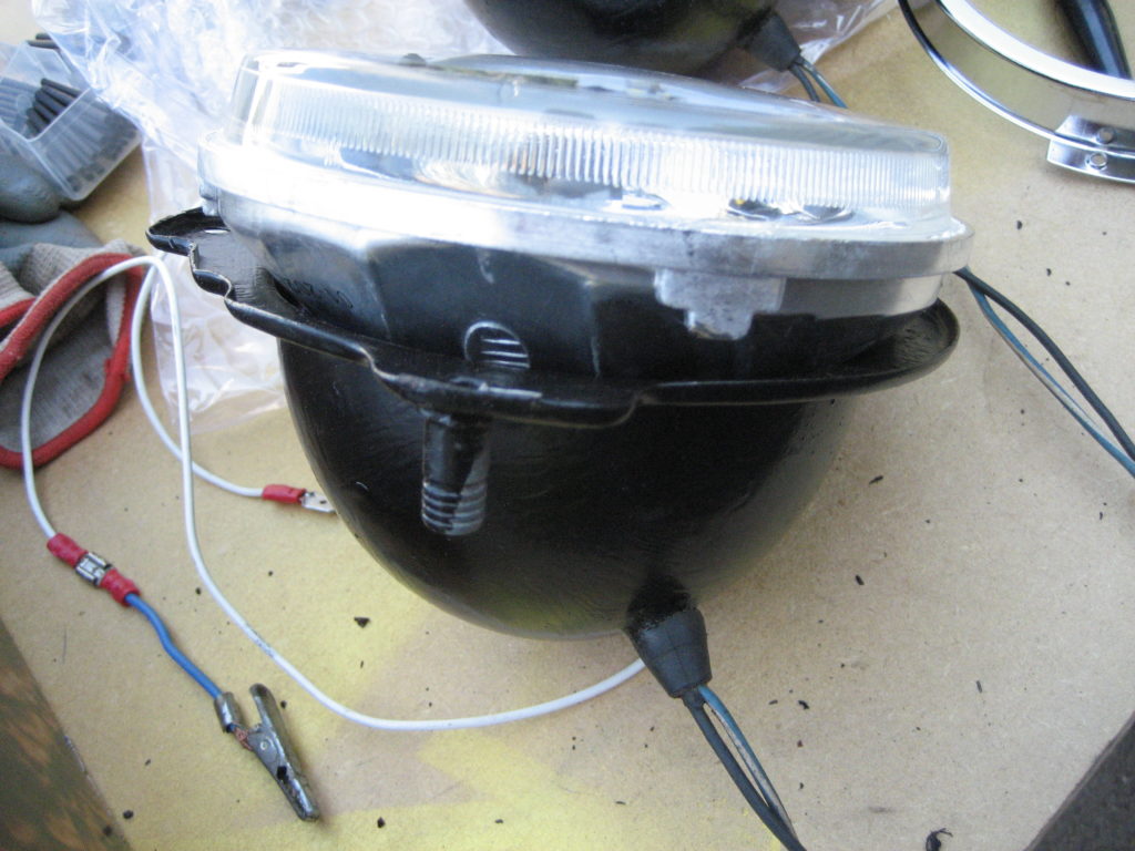
The new headlights from MK1 arrived – very nice – and they fitted within the steel bowls, so I started the process of putting them in place. Firstly I replaced the plastic raw plugs with the proper “nylon nuts”, and wired in H4 lamp connectors. I’ve used H4 for all 4 lamps, wiring the outers to dip and the inners to main beam. Many use H1 as the inners, but I perfer to use the same bulb type throughout – less spares to worry about.
You can see from this picture (courtesy of Rimmer Bros) how the lamps fit together. I would have saved a lot of time, had I looked at this first.
The light units are sandwiched between the outer chrome ring and the inner steel ring, with adjustment being provided by moving the inner steel ring via the aduster screws. I made the mistake of assuming that the light units fitted between the inner ring and the steel bowl. I wondered why the light units didn’t quite fit, and thought that it was just because the new lamps were pattern parts. The inner rings clamped the light units tightly enough but they wouldn’t fit flush with the front of the ring so adjustment was really difficult and not accurate enough for an MOT.
As I wasn’t happy with the fit, I took them off again and checked the manual. Fitting them the second time, and in the correct way led to much better results. Just as I had hoped. I’ll adjust them again on one dark night this week. Then I can put the grill back on.
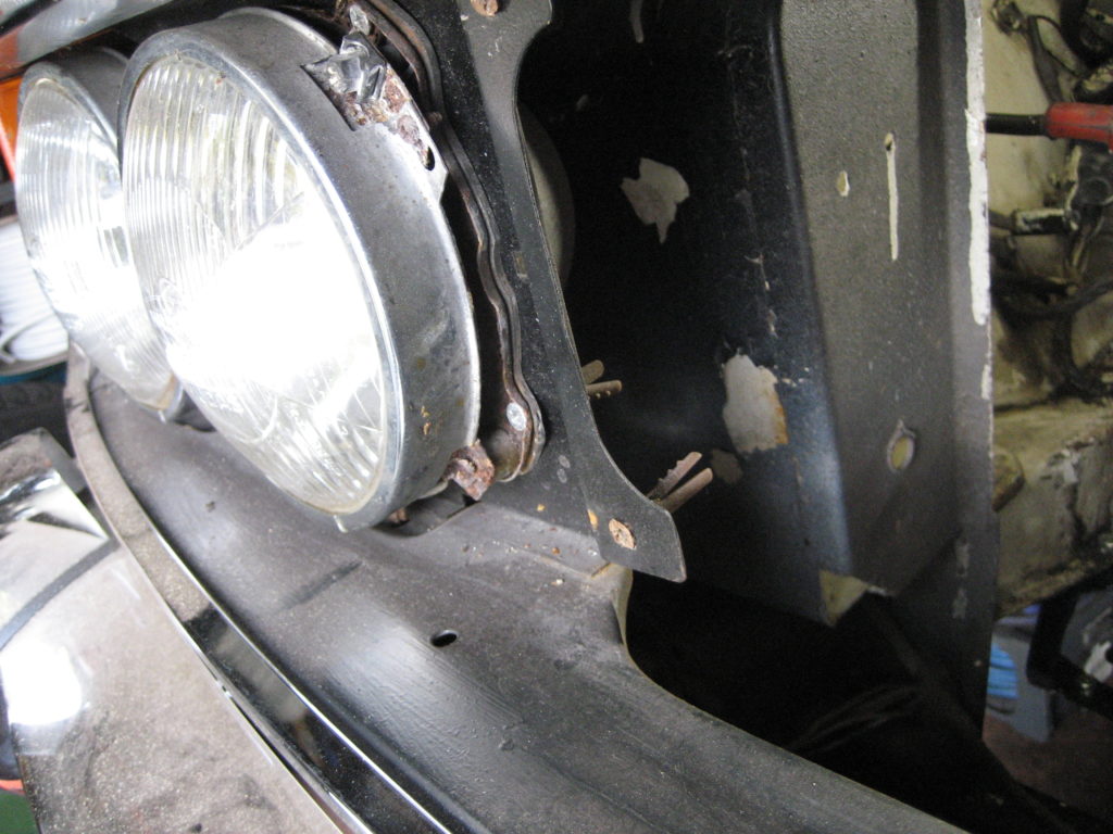
I am amazed sometimes by what some restorers do to old cars. I could see the reflectors were rusted so I removed the grill segments to get at the headlamps. What I found was that the headlights and grill were held in by wood screws and rawplugs. Ok – 10 points for inginuity, but I couldn’t live with it. So out it all came.
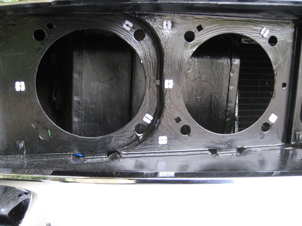
The reflectors on all 4 headlights were shot, so I found some “like for like” replacements on E-Bay (Crystal Halogen). Whilst I waited for delivery, I cleaned up the original steel headlight bowls and gave them and their surrounds a new coat of paint. Unfortunately when the new lamps arrived they didn’t fit into the refurbished bowls, so they went back and I ordered some more (MK1).
Worse still I found the wiring for the headlights consisted of stripped and twisted copper with no insulation, where someone had patched in replacement sidelights. This was a vehicle fire-ball waiting to happen. The wiring junctions have all now been replaced with insulated terminals.
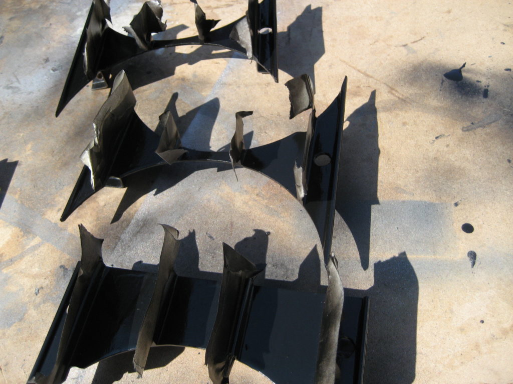
So while I wait again for the next set of lights to be delivered, I thought I would re-paint the grill segments. After cleaning they were tricky to mask, but the end result looks pretty good.
There is always a snag when doing almost any job on a Stag. The snag here was the grill badge. Both retaining bolts sheered when I removed it. I happened to find a couple of M4 replacements in my spare bolt box, so I drilled and tapped two replacement threads – good as new.
With the cooling system now upgraded and all the fluids back in place and topped up, I ran the engine to temp to check everything was working. 3 problems:
The top hose poped off once the engine was warm;
There was a fuel leak at the joint of the steel fuel pipe and the rubber hose at the rear;
There was a puddle of fresh oil.
The first 2 were easy fixes – done in a few minutes. I did some research on the third.
There are some usual suspects when it comes to oil leaks on a Stag. The cam covers can leak through the cork gasket, the half-moon rubbers or the cam cover screws. Underneath the oil pump has two internal seals that can leak along with a 3rd between the pump and the block. Then there is the oil transfer housing that also has 2 seals that perish and/or harden over time and cause leaks. The final source of dripping oil after a run, is the rear crankshaft oil seal.
The rear crankshaft oil seal is the most onerous to change as it requires the gearbox to come out first. Not something to contemplate until all the others have been sorted first.
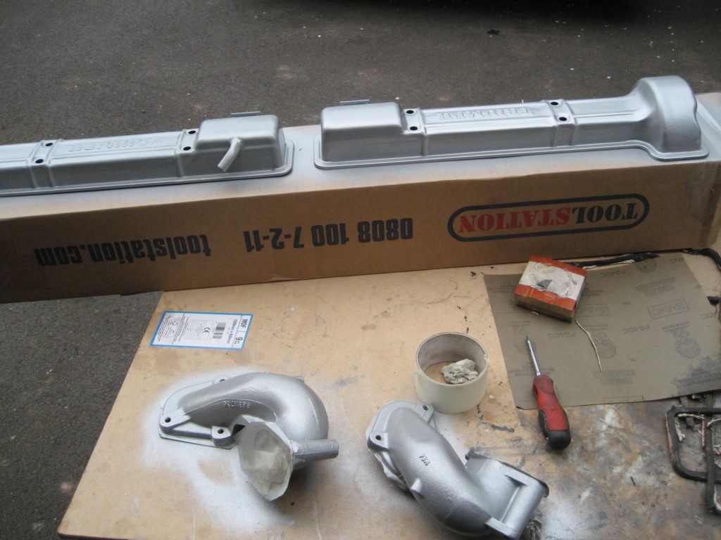
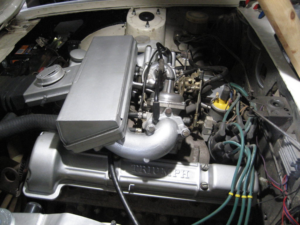
I started with the cam covers. They came off easily although thet need some cleaning internally as the gaskets had been held in place with silicon sealant. Having removed all of the sealant I decided to give them a new coat of paint along with the air intake elbows.
As these were drying I tackled the oil pump and oil transfer housing. Neither can be done from above – you have to get underneath and also remove the right hand exhaust at the manifold. You need to remove the oil filter first and then you can remove the oil pump and the transfer housing.
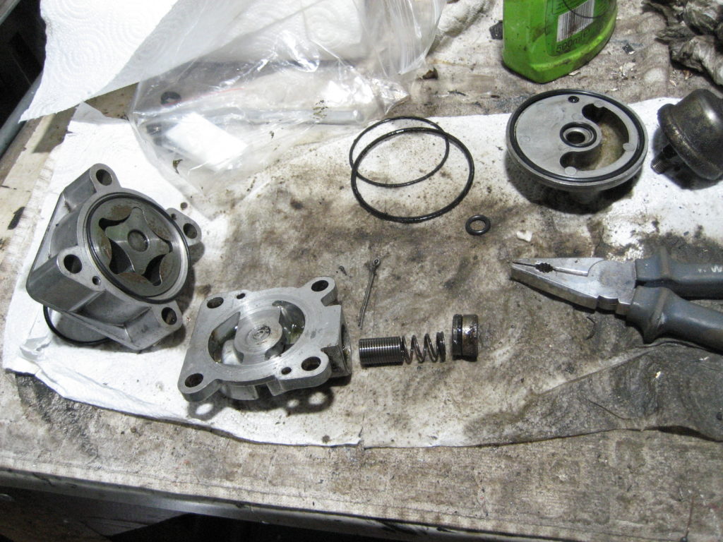
Replacing the seals is straight forward once the pump and transfer housing were cleaned. I did have a little trouble trying to figure outwhich new seal was which as they came all in one back together. In the end I stripped the pump and housing and laid out all of the old seals next to the new.
While I was had the pump in bits I also replaced the drive shaft. The old one had very little wear but I didn’t know that until it was stripped. As they are so cheap, I bought a new one just in case, and replaced it anyway.
The trickiest part of this particular job was replacing the transfer housing on the block. My stag is an auto with the BW35 box. The clearence between the Bw35 breather pipe and the oil sensor which is screwed into the top of the oil transfer housing is very tight. After half an hour of profanities, I managed to get it installed by
Sticking the sealing ring into the recess in the housing using a little flexible gasket sealant – as it kept dropping out of position;
Starting the thread of the oil sensor into the housing before refitting the housing – I couldn’t start the thread with the transfer housing in place, there just wasn’t room;
Disconnecting the sensor wire and re-connecting only after everything was tight.
I’ll re-asseble the cam covers tomorrow and turn the engine over to see if i’ve cured it.
Cam covers back on, but I haven’t turned her over. The reason – I used a very thin smear of gasket sealant between the head and the cork gaskets. Mainly because the half moon seals stood a little proud of the block, and I wanted something to fill a potential gap if they didn’t compress when I tightened the cam covers up.
I will leave it all to settle and seal and start it next weekend.
Update – 26th April 2020
After the remedial work last week, I turned the key again. The re-connection of the radiator hose to the pump, had re-positioned the lower segment of the pipe so it interferred with the alternator again. This time I drained the coolant, removed the lower rubber segment and shortened it by a centimeter. When refitted this moved the pipe assembly out of the way of the alternator fan.
I ran it up to temperature once more – all well and NO OIL PUDDLE – success!!.
The automotive trade press has been dicussing this topic for many, many years. Namely, the problems with the Stag cooling system that caused the engine to overhead and the heads to warp. From the many articles I have read and the many knowledable folks I have spoken to, this was not an inherent design flaw, but more a symptom of poor build quality, followed by even worse ongoing maintenance.
The root cause, in many cases, was that casting sand was not fully flushed from the block during production. As the engine was in use, the casting sand migrated into the radiator and slowly silted it up, greatly decreasing it’s efficiency. Alongside this, the inherent electrolytic reaction between iron and aluminum at the heads also became a problem if the coolant didn’t contain inhibitors that prevent it.
If the radiator and coolant was regularly flushed / cleaned / replaced, then these V8s ran fine, and of course sounded georgeous with that off-beat firing order.
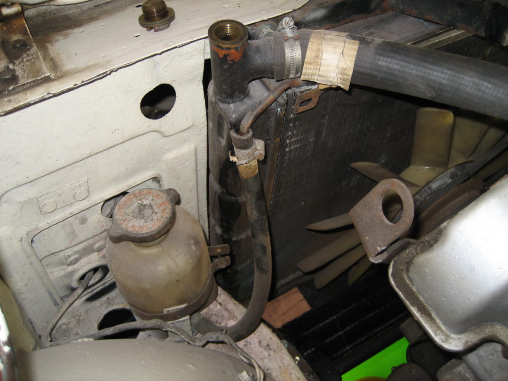
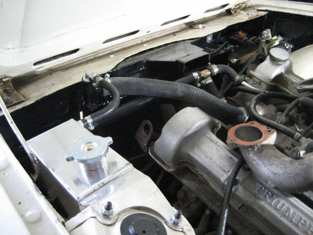
Anyway, it was time to refurbish mine. I removed the radiator and flushed it clean inside, then gave it a coat of paint to tidy it up along with the air intake duct above it. Whilst the radiator and pipes were out of the way, I also painted the inner side of the front valance and the headlamp panels.
Another issue with the Stag engine (not mentioned above) is the positioning of the waterpump. If the cooling system is kept in good order then this feature of the design doesn’t present itself. However as the car ages and the pipe joints get a little worn and tired, then air can leak into the cooling system. The water pump happens to be the highest point in the circulation system, so this is where the air ends up. Spinning a dry pump never ends well.
To help prevent the above, I have purchased a complete set of new hoses and a StagWeber Header tank, alongside the fresh anti-corrosion anti-freeze. Re-plumbing took a few hours, not because it was complex but mainly to position the header tank correctly and the make sure the lower radiator pipe was positioned so it didn’t snag the alternator or power steering – tricky.
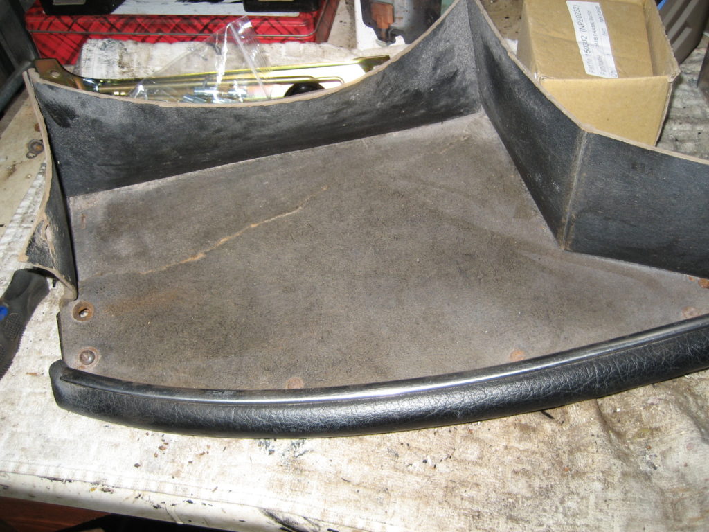
The parcel shelf under the glove box on a Stag is another weak point. It is made of little more than cardboard, and 47 years on it is looking decidedly worse for wear.
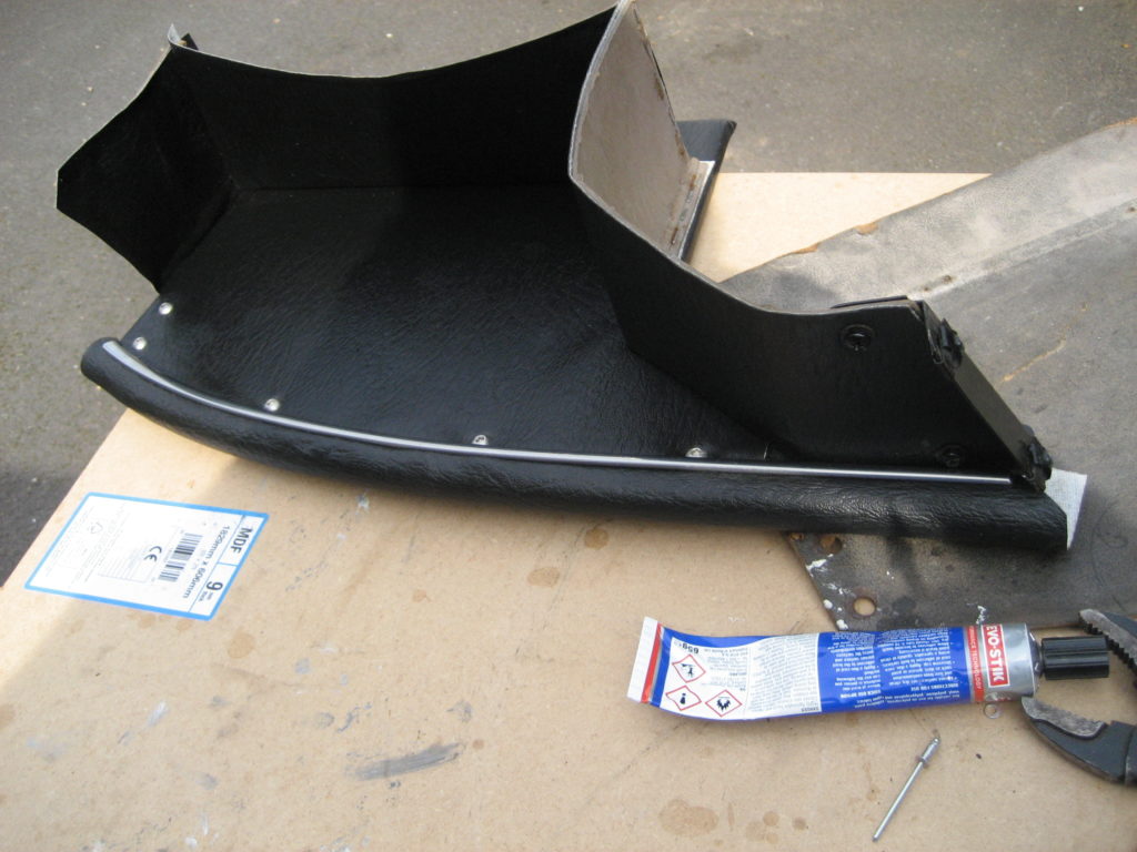
Instead of replacing like-for-likefrom Rimmer’s Catalogue, I thought I would upgrade, by making a new one from MDF and some spare vinyl. A little time, some evostick and an industrial stapler later, and I think it looks better than the original (and is definately more robust).
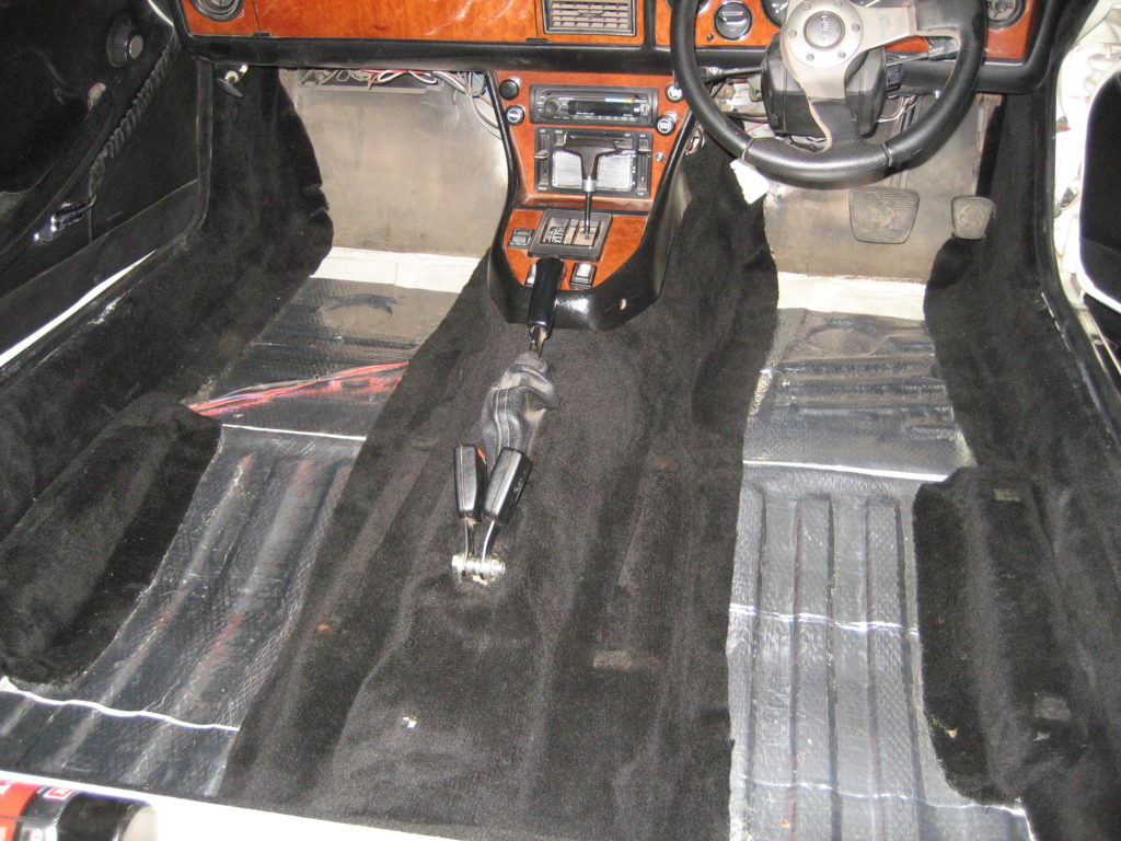
I wanted to get the parcel shelf back in before I finished the carpets and put the front seats back in. It’s much easier to install when you can lay in the car, rather than leaning over the passenger seat.
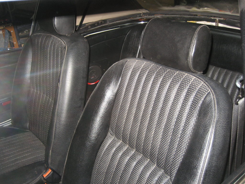
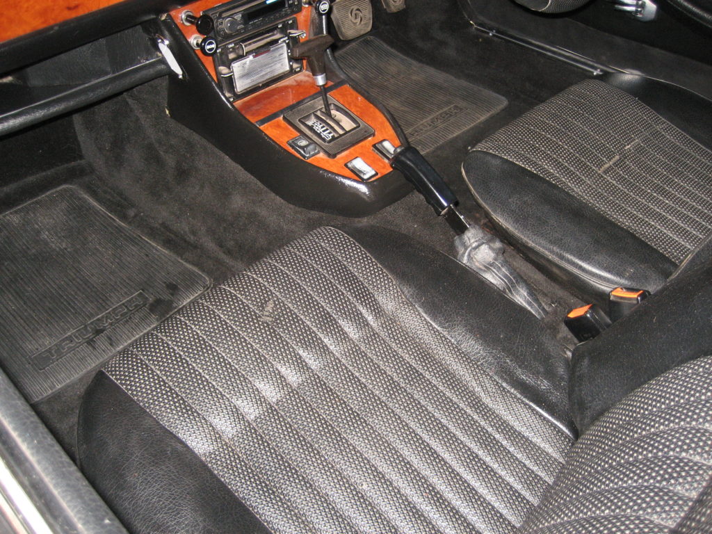
Re-trimming the cabin didn’t take too long once it was in. I had already done most of the hard work in the reburb and cleaning. With everything back in and sparkling, my eye is drawn to the small rips in the drivers seat covering. When I refurbished them, and in the context of the car as it was, I thought I could live with it. Now everything around it is clean and tidy once more, it stands out.
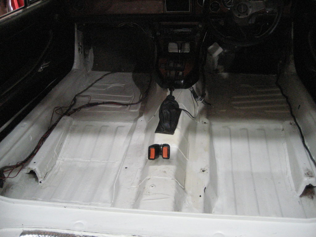
I am amazed how much dust and crud is generated by an angle grinder. The inside of the Stag was a real mess. So out it all came – well what was left anyway. Then the vacuum cleaner, detergent and a coat of epoxy paint. Looks better already.
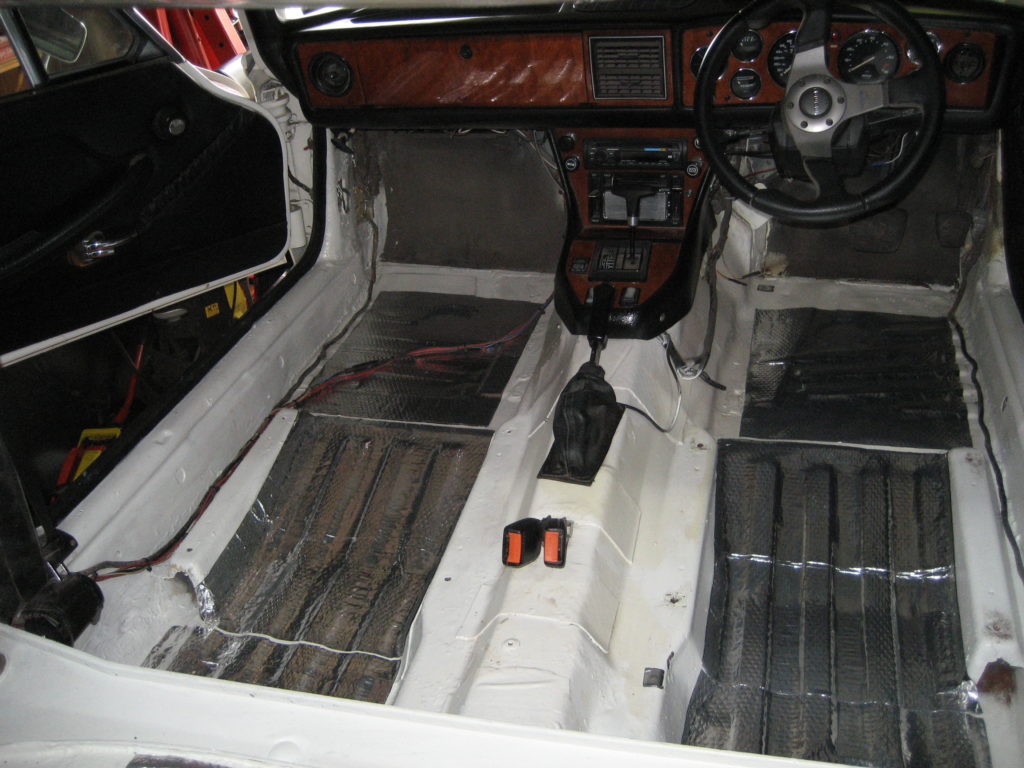
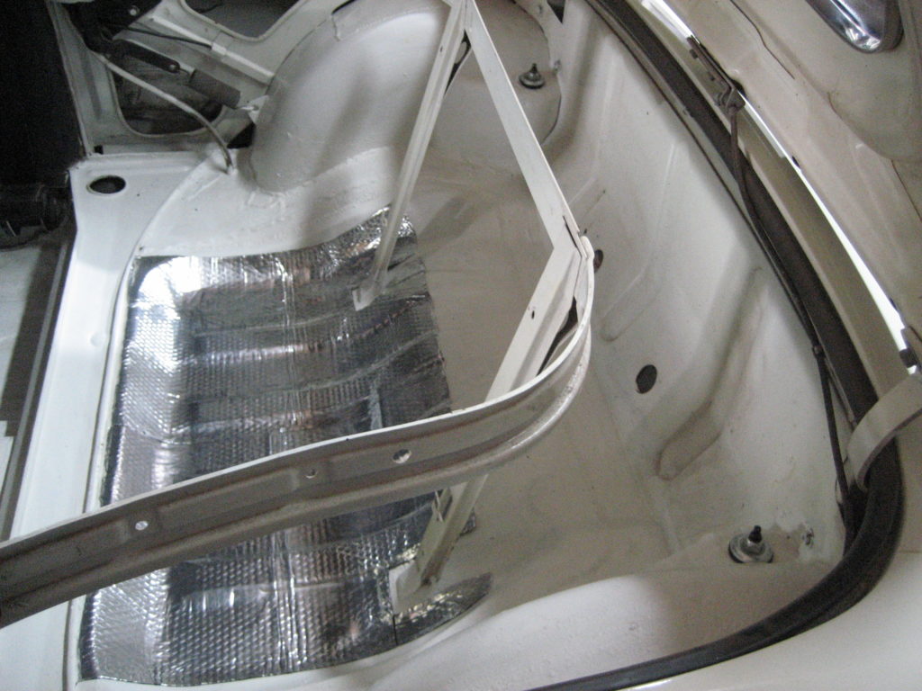
With all of the welding and panel replacement, the sound deadening pads were removed along with the rust. Rimmers are rather expensive so I sourced some via Ebay. Much bigger sheets, so I’ve covered both passenger and driver floors and under the rear seat.
Next the carpets. My wife was horrified when she found me. In the kitchen, sitting on the floor, with all of the Stag carpets around me, and her precious carpet cleaner. They came up a treat. A few bare patches but nothing so bad as I need to spend £500 on new. I used some spray-on Evostick to place the edging peices.
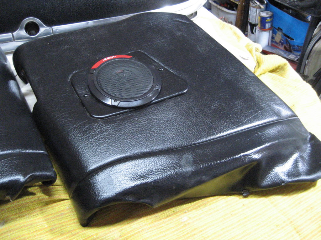
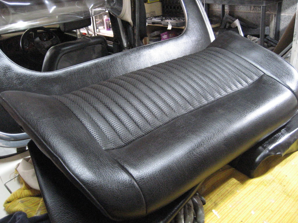
While the glue was drying, I turned to the seats. I have already refurbed them, but they got covered in crud over the last few months work. A good clean later here they are along with the rear side panels where I also installed a couple of speakers.
Well the country is pretty much on lock-down now. Covid-19 is wreaking havic in Italy and Spain and I fear we are a week or so behind them. I’ve not been out all week as I am lucky enough to be able to work from home. Whilst it’s a little un-nerving as life as we know it is changed so drastically so quickly, if isolation saves lives and heartache then that is the least I can do.
The self isolation has given me far more time than normal to play in the garage this weekend. I have now completed the re-assembly of the rear axle and suspension as well as re-fitting the exhaust.
On the drivers side I tried fitting the drive shaft as a single item. Unfortunately the dust cover wouldn’t be forced through the apperature in the trailing arm. So back to plan A, or more accurately before Plan A, because I hadn’t realised how closely paired the inner and outer shaft were. I had heard that they came in pairs but didn’t fully realise the significance. The inner and outer shafts are machined to fit each other precisely. An inner shaft from one pair may not fit an outer from another pair. That’s what happened to me. I must have mixed up the pairs and one pair would not mate up easily. So the passenger side had to come off again.
This time I didn’t attach the inner drive shatf flange to the diff. It was the easier to slot the inner and outer shafts together this way, but more difficult to torque up the flange bolts afterwards.
For the timebeing I have decided to live with the existing exhaust. It hasn’t got that stainless steel snarl I love, but there is nothing wrong with it (although I couldn’t tighten one of the manifold studs). So it’s gone back on for now.
My plan today was to build a new set of gates for my Mom in Wales. Her’s had rotted and blown apart during th recent gales, so I thought I would pop over, take her for a nice Mother’s Day lunch and start building the new gates. Covid 19 has put paid to that as my Mom is 78 and therefore in a vulnerable group. Next on my list was a game of golf as the weather was forecast to be clear and dry. Although the Golf Club was open, it is not essential travel so, in line with the current guidence, I haven’t travelled. So, it was back to the garage – what a pity 🙂
Todays job was to start the re-assembly of the rear suspension. Starting on the passenger side, my aim was to build up the suspension gradually on the vehicle, rather than assemble it off the vehicle and then fit it as one peice. My reasoning was simple. I am doing this by myself with my limited equipment in a domestic garage. A complete rear suspension is just too heavy and cumbersome to move around when you are solo.
Anyway, the first task was to re-couple the trailing arms to the rear sub-frame arms. I had already replaced the bushes so this only involved a little silicone spray and easing the bushes into the steel brackets on the already assembled and painted sub-frame arms.
Then I fitted the trailings arms and sub frame to the quill shaft sub-assembly with the aid of my small trolley jack. Next I connected the inner drive flange to the diff and torqued the 4 bolts up tight. The sequence of re-assembly I chose was because I thought that it would be easier to torque up thes bolts whilst I still had reasonable access. It was, but aligning the inner and outrive shafts was not easy later on.
The main sub-frame bush was connected next through the car body and the ant-vibration strap. Follwed by the outer drive shaft, gaiter and dust cover. As I mentioned above, the precision nature of the inner and outer drive shafts makes it difficult to mate them together whilst also supporting the weight of the hub and brake assembly. I may try assembling the full drive shaft / brake assembly and the trailing arm before I attach to the diff on the driver side – it may be easier.
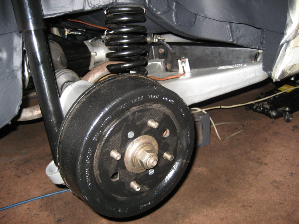
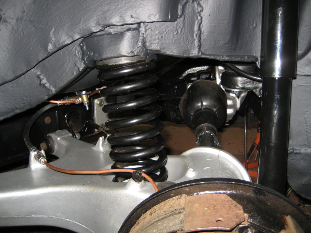
Finally I installed the new spring, mounting rubbers and shock absorber. I didn’t have time to torque all of the bolts or close the gaiter with tie wraps, but I was very happy with the progress today.
It feels like I’ve turned the corner. All the welding is done: chassis and floor panels. The under-side has 2 coats of Rustbuster epoxy mastic paint and 2 coats of stone chip. Its now time to start putting the rear end back together.
First was a replacement brake pipe between the PDWA and the 3-way connector under the boot floor. Whilst the propshaft was missing, this was quite a straight forward job, especially since I had purchased some new brake pipe / fuel pipe clips and simply replaced the existing ones along the transmission tunnel.
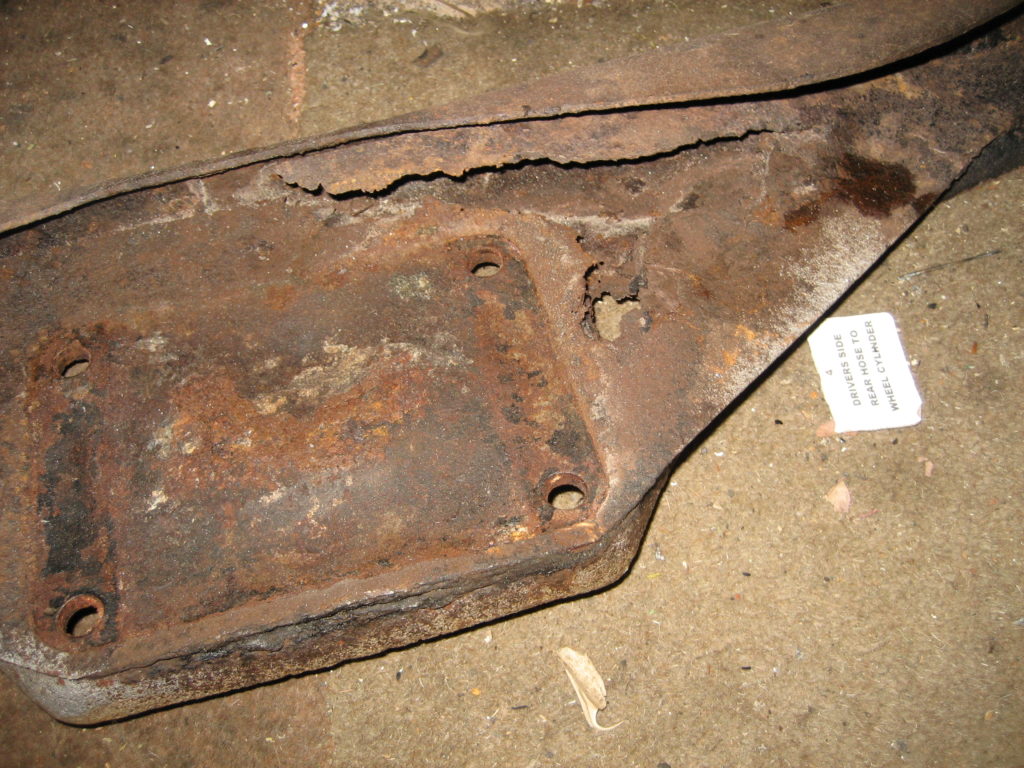
Now to the differential and prop shaft. The photo below is the old diff mounting panel. It was scrap along with the backplate of the diff itself. I found a second hand mounting panel, cleaned it up an painted it. Then swapped the diff for a reconditioned one. As you can see, it looks as good as new now.
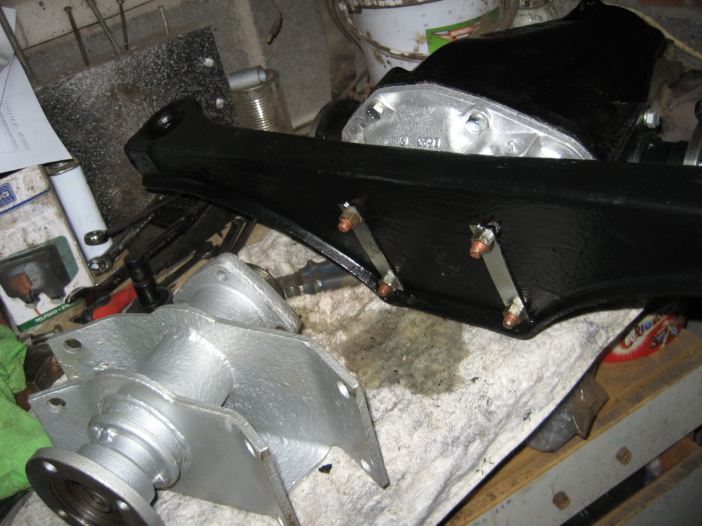
As I mentioned in a pevious post, I had already refurbished the quill shaft assembly, so once I had mated the diff to the mounting panel, I attached the quill shaft to the other end. I then torqued up the bolts to the settings in the service manual – see the Torque setting page.
With the aid of my trolley jack, I manouevered the assembly into position under the mounting pins and sandwiched the mounting panel at both ends with new rubber top and bottom mounts and a shiney new lower washer. With the jack taking the weight it was simple to add the 1/2″ nylocs and torque them up. I left the jack taking the weight and re-connected the prop shaft.
I torqued up the 4 connecting bolts to the right settings and managed to damage my left shoulder in the process. The problem was that the torque wrench has a much longer handle than my 1/2″ spanner, and since the prop shaft was able to rotate, my left arm had to mitigate the torgue produced by the longer torque wrench whilst lying under the car. Ouch. That’s enough for today.
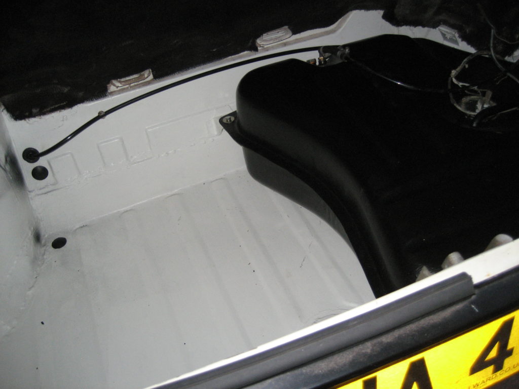
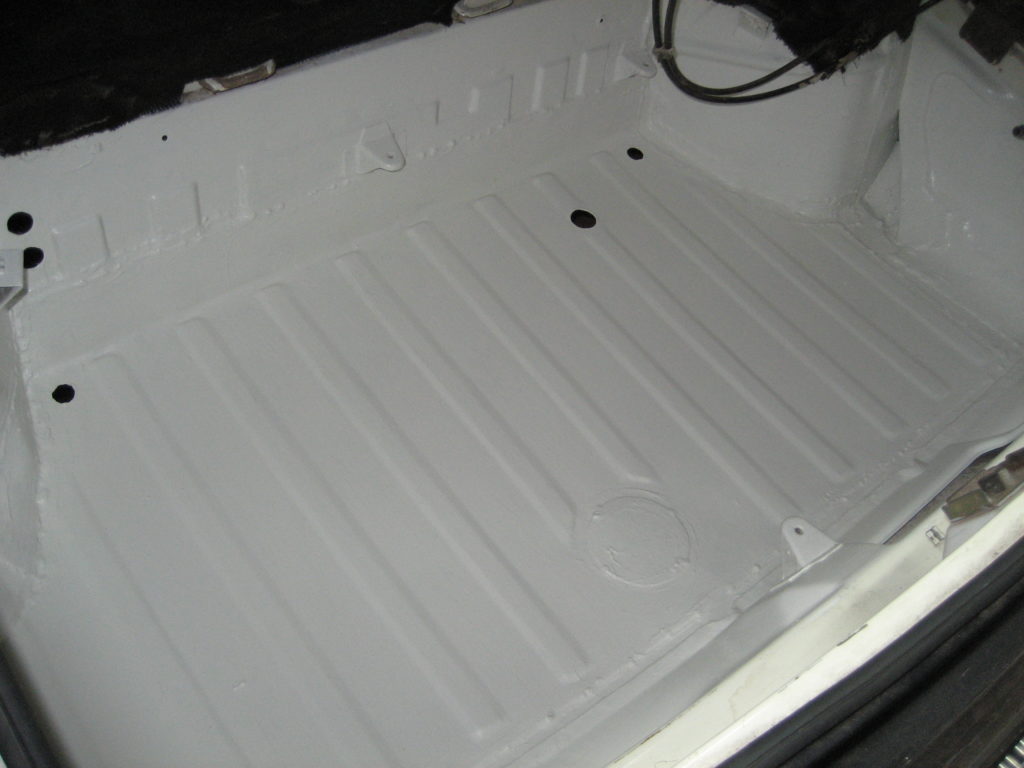
Now the boot floor has been replaced and the new steel boot floor painted (inside and out), I could now replace the re-furbished fuel tank. Arry the Stag had a recent feature on rusty fuel tanks. Interestingly TR Tony chose a similar method to repair his tank as I had used – see earlier post. During his short video I noticed the routing of his fuel pipe from the fuel pump to the carbs. It was routed through the boot floor under the right-hand corner of the fuel tank.
I tried the replicate this routing but found that the nylon fuel pipe would kink if I tried to force it through 90 degrees as it passed though the grommet in the boot floor. Instead of routing the fuel pipe externally along the rear of the boot, I bought it into the boot through the upper hole in the left hand corner of the boot rear panel, then along the inside of the boot to the pump. There seems much less stress on the nylon pipe this way and therefore less risk of fuel starvation should it kink in future.
As with the Rear Seat Pan, the boot floor was rusted through in a number of places. The worst spot being under the fuel tank where any water getting into the boot eventually gathered. This area was so thin the grit blasting had peeled it opened, allowing the grit to rupture the fuel tank as well.
I chose to take the same approach as for the rear seat pan i.e. cutting away the rusty old panel about an inch from the side walls, and laying the new panel on top of this newly created lip.
To complicate matters I found the rear of the passenger side wing also needed patching, which I did before shaping and welding in the new boot floor panel.
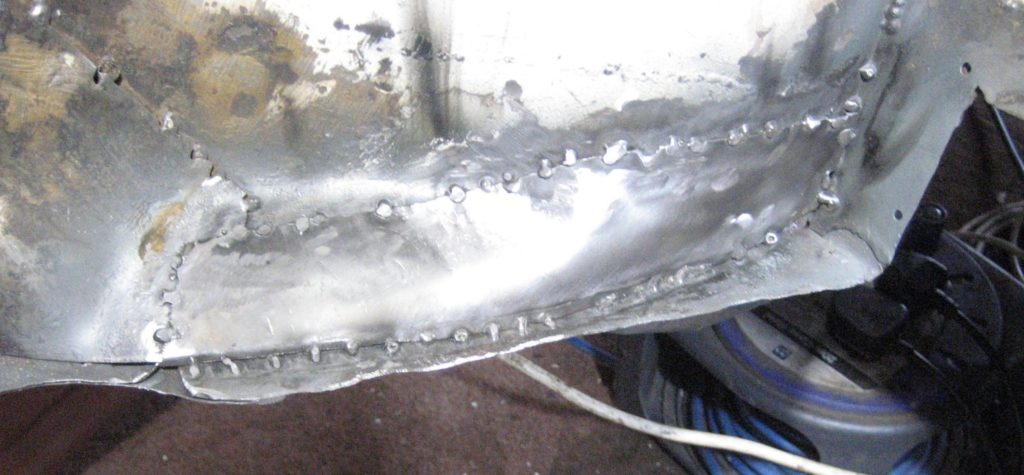
As with the Rear seat pan, I welded top and bottom and then covered both sides with FE-123.
I am quite proud of the end result here too. Having just learned to weld I don’t think I’ve done to badly especially since half of the welding was done on my back welding against gravity and on thin steel.
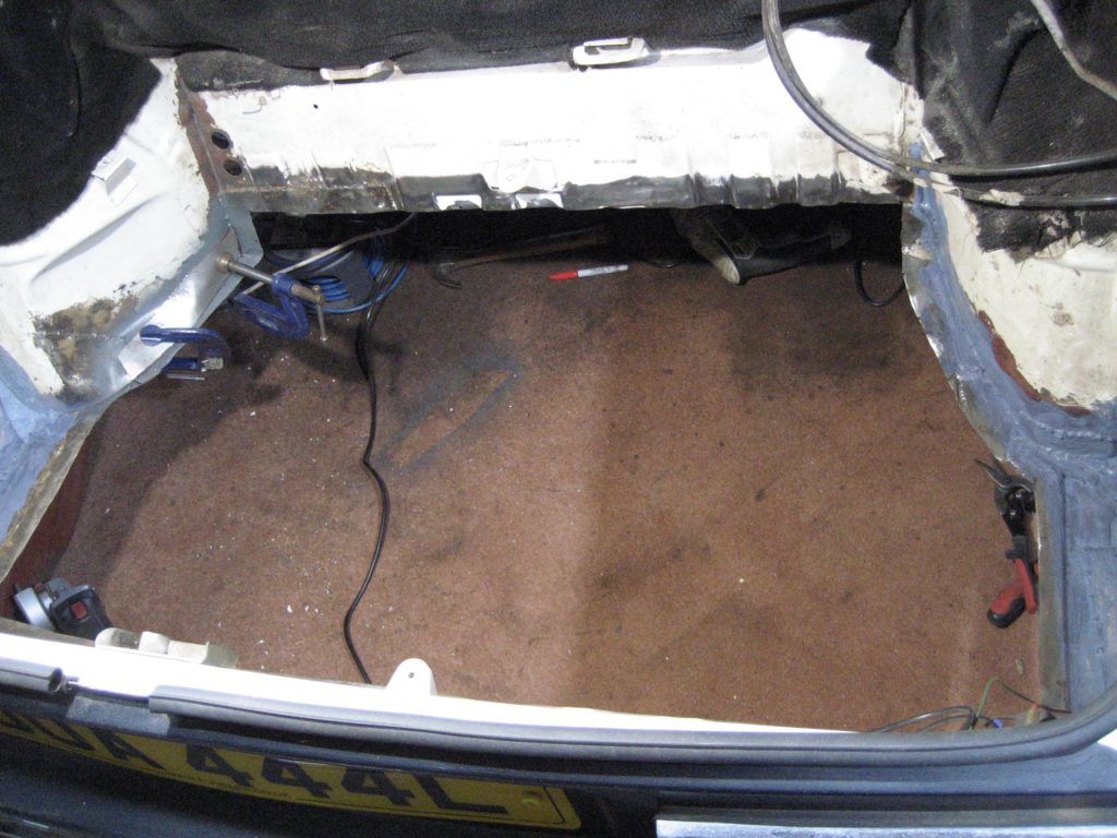
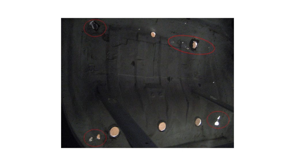
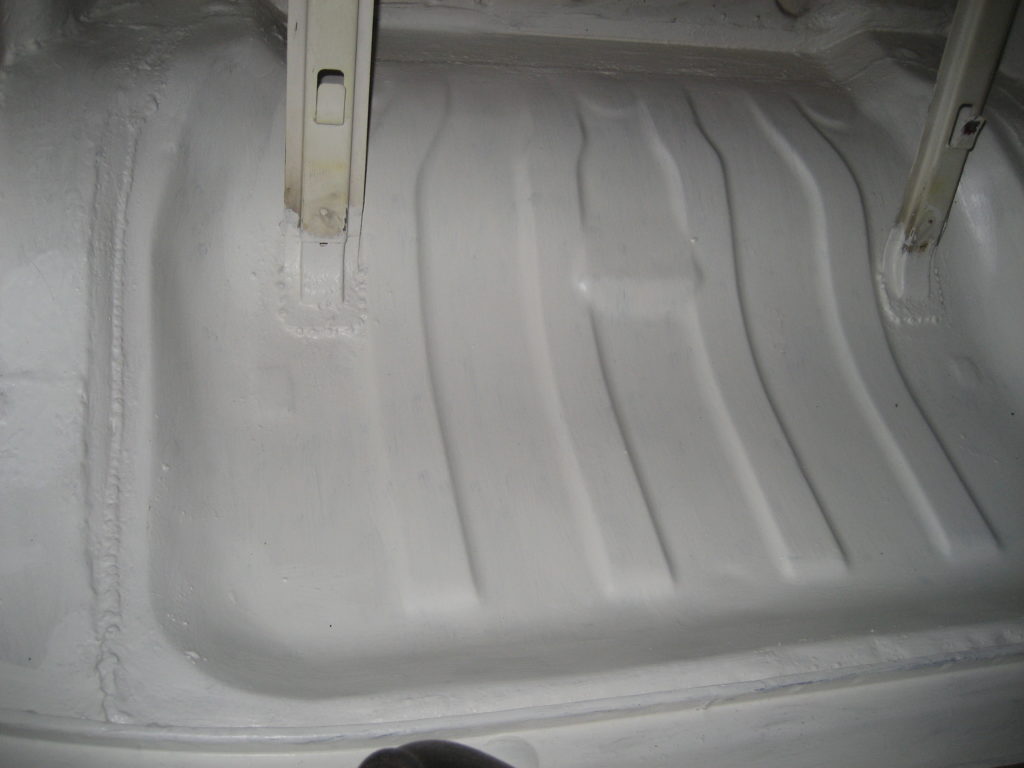
With my work light under the care, it didn’t take much to realise that the Rear Seat Pan was pretty much scap. The rust had badly perforated the four areas I have cicled, and in others it was only the sound deadening sheet that was holding the pannel together.
Then I realised that these panels are no longer available. Rimmers don’t carry them and nor do the others. So I posted an SOS on the Stag Facebook forum. Luckily for me another Stag enthusiast (Darren Capper) had a panel he was willing to sell. It was pressed some time ago and had sat in his garage.
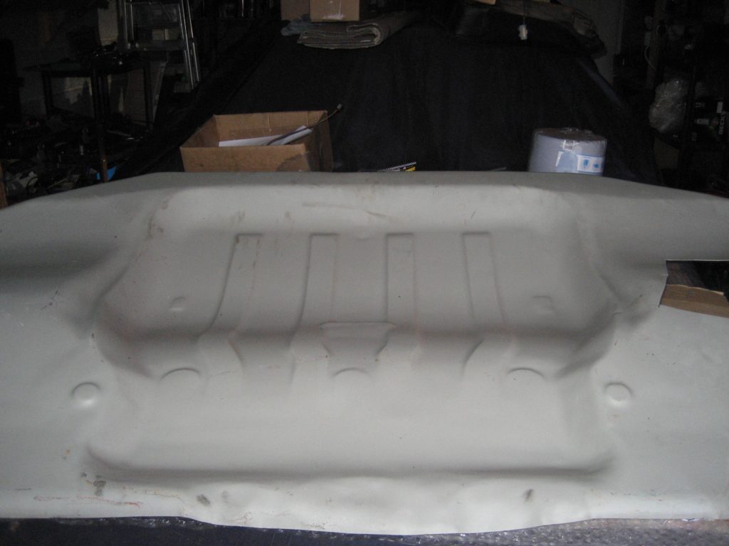
As you can see, it was a raw pressing without even having been cut down to size. But that was fine as I was going to cut it down anyway, based on the rusty section I was removing from my car.
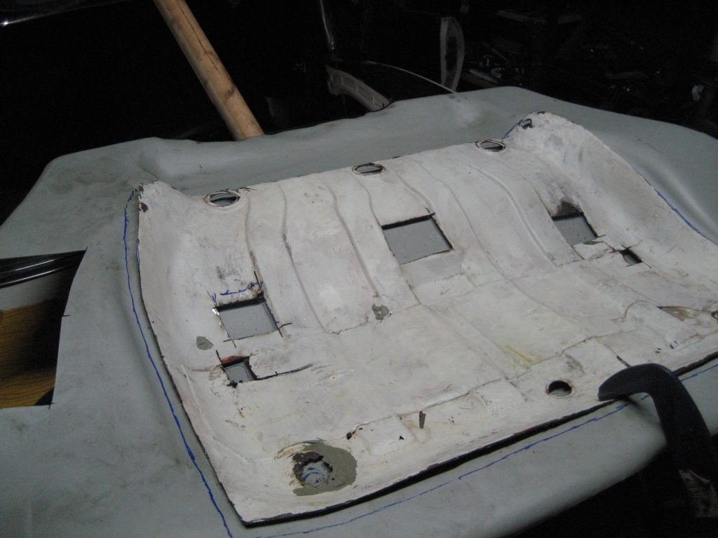
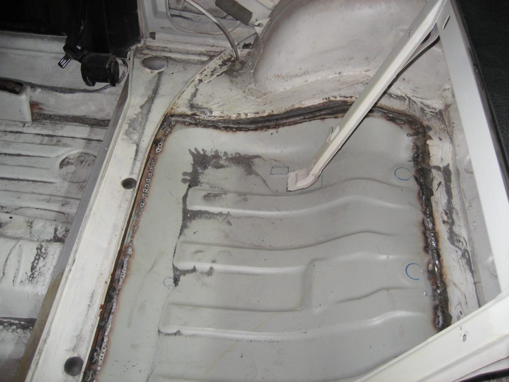
The installation method I adopted seemed logical to me, although the purists will probably not approved. I removed the section of the panel that was essentially scrap, and used it as a template against the new panel. I cut the new panel with appox 2cm clearence around the old one. This meant that the new panel, when dropped into place from inside the car, would sit on a lip of circa 2cm all around. I welded from above and underneath i.e a double welded joint all around. Not pretty but strong.
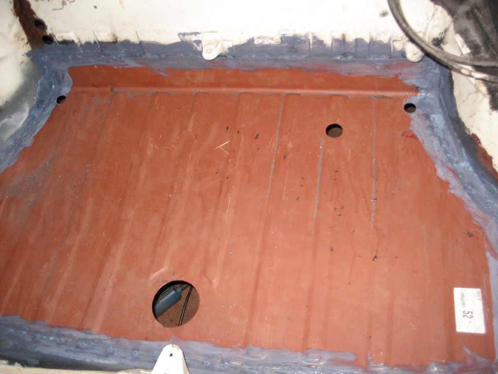
Once the seam sealer had been applied and a couple of coats of my favouratie Rustbuster epoxy white paint I thought it looked pretty good. Not perfect I know but strong and better protected than the original factory fitted one. As that had lasted 47 years I think this oone will last be out.