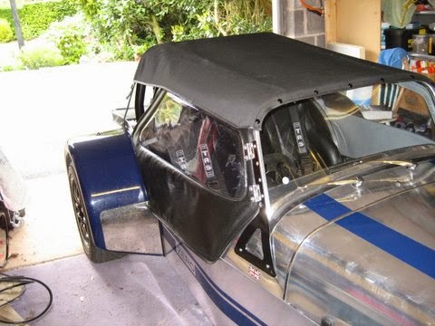
Having already procured a reasonable front and rear tub, I placed the existing tubs on Marketplace for a nominal amount. It was a surprise to me the interest the add generated. The philosophy behind the add was to find it a good home at minimal expense thereby avoiding the time and effort of chopping it up and scrapping it. In the end It was fetched and I was £100 better off. Everyone happy.
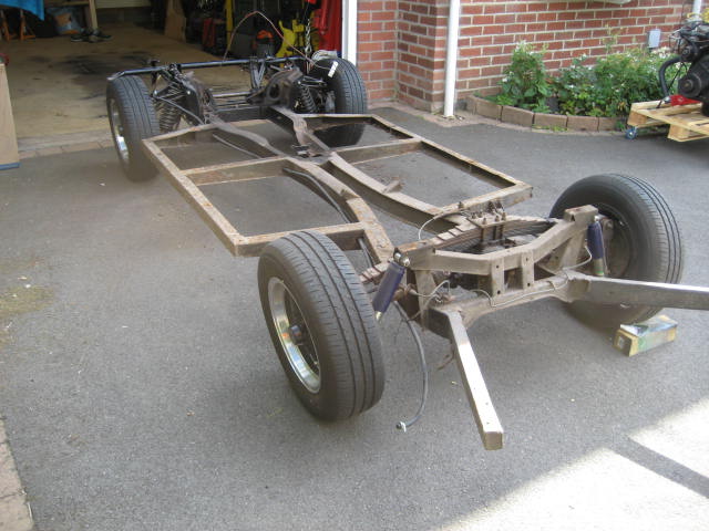
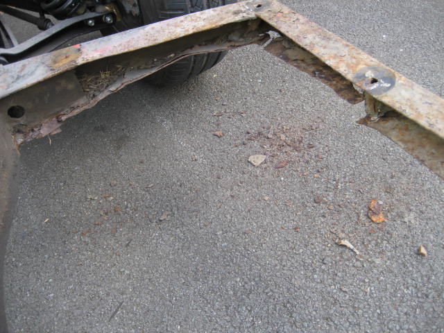
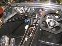
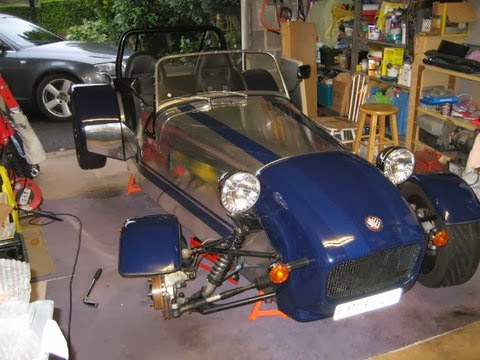
With the body now off I could take a good look at the chassis. After a cursory look from underneath a while ago I noted that both front outriggers were rotten along with the side chassis rails. I bought a refurbished chassis from a 13/60 along with the refurbished front and rear tubs in anticipation that the chassis was scrap. Looking at it now, I find that its not that bad. Yes the front outriggers and side rails need replacing but that’s about it. Well worth saving and in fact I think I will use it rather than making the possible adjustments to the replacement 13/60 chassis I bought, that would be needed for the Vitesse.
With the car now dismantled down to it’s chassis there is no point in simply replacing the chassis components and rebuilding without removing and refurbishing the suspension and running gear. Its “All In”. The final decision as to which chassis to use can be made once it is completely bear of components and can be stripped/sand-blasted. So on with the disassembly.
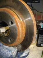
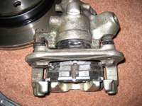
Starting with the rear I removed the brake pipes and hand brake cable, making a note of the pipe routing. Next was the drivers side rear suspension. Previous owners had already upgraded the shocks to Gaz adjustables and all of the bushes had been replaced with polybushes. However that Is as far as the refurbishment went. The rear hub and drive shaft looked original and showing its age. In fact I had to hacksaw free the radius arm bolt to remove it as it had seized inside the new bush.
The passenger side was a very similar story including the need to hacksaw free the radius arm bolts. I tried to remove the bushes from the radius arm but failed. I will need to find someone with a press to push them out.
The rear leaf spring was next to be removed. Even without the wheels there was still quite a bit of tension in the spring as I released bolts to the vertical links. I might be a bit of a struggle to get it back on.
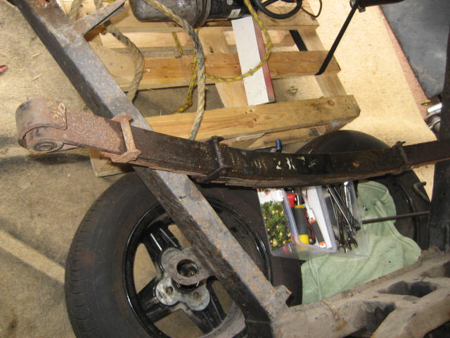
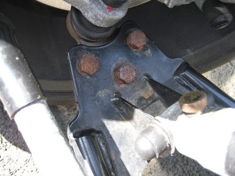
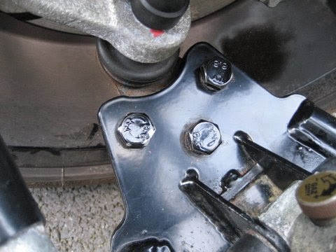
Thankfully all of the extended length studs came out easily that hold the spring to the top of the differential but I noticed that the “Top Retaining Plate – 128352” had snapped in half, so that will need replacing.
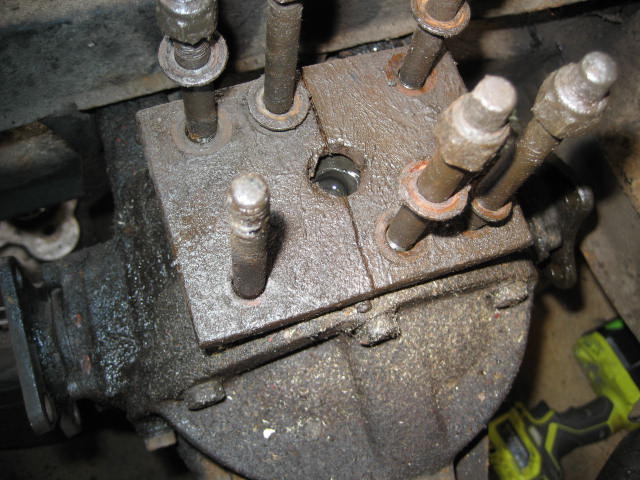
The differential itself looks original but there was a lot of leaking oil so it will probably need new seals of a recon.
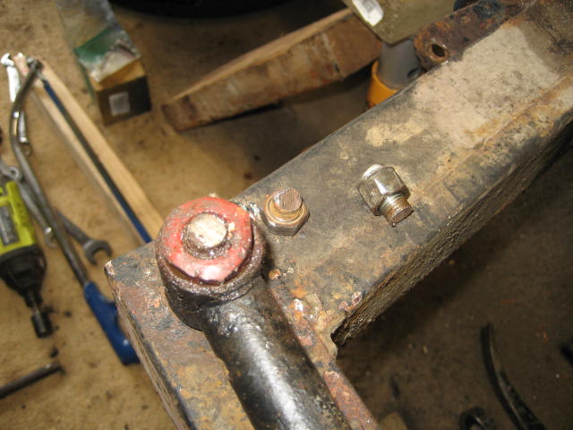
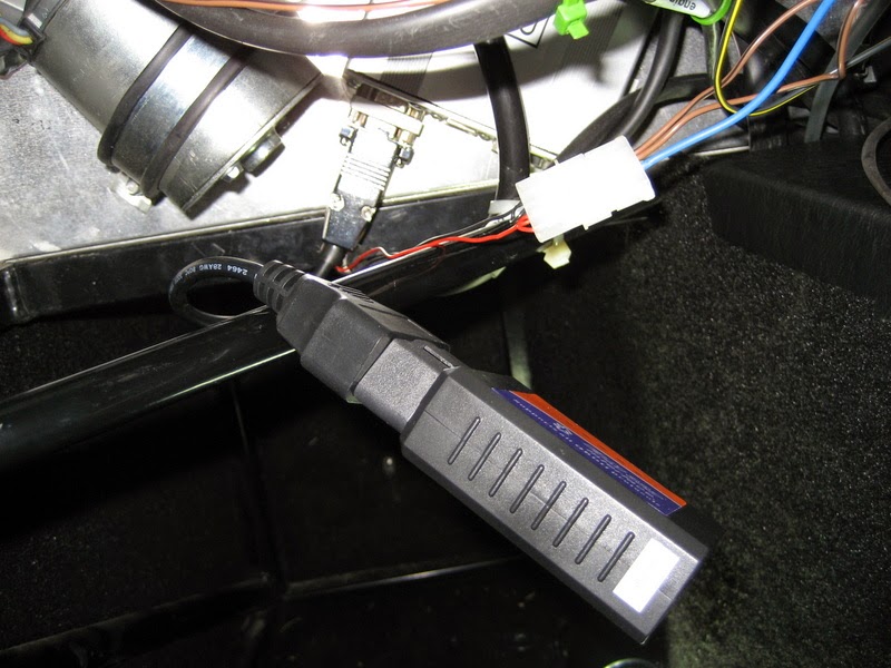
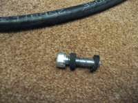
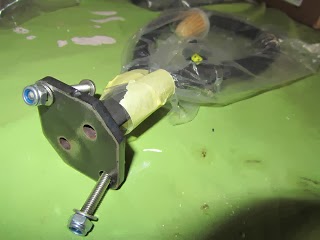
With the rear chassis now stripped bare it was time to start on the front. Firstly the anti-roll bar and then the steering rack. After a few heavy blows to the right side track rod end it wasn’t budging. I needed a proper joint puller to break the morse taper. Amazon delivered me a complete set next day (here’s the link). With the right tools the steering rack was off in 10 minutes.
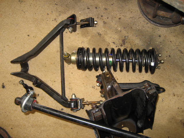
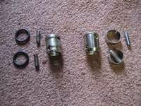
I found that the front suspension components were new which was a nice surprise. No need to replace the shocks, bushes, wishbones of springs. Because it was new it only took a short while to disassemble leaving a bare chassis. As a note to self – each wishbone mounting bracket had 2 shims – 8 in total.
So that’s the disassembly of the major components done. So now to the more time consuming part – the recommissioning and reassembly.
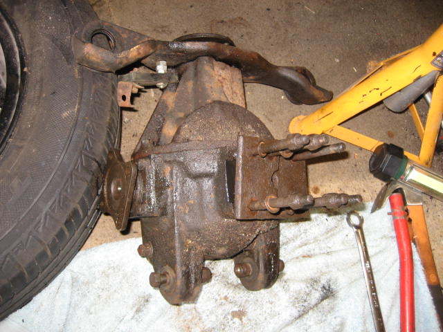
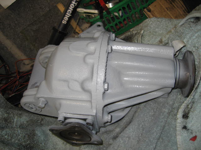
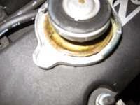
As I had a few hours available I thought I would degrease the diff and diff carrier. Under the layers of grease and oil I was surprised to found a refurbished diff. Stanpart V2734, number FH167531 with a ration of 4.11. All correct for a Vitesse of this age. I could tell it had already been refurbed because of the plastic oil seal around the pinion bearings and the missing castellated nut and split pin which had been replaced with a standard nut.
After degreasing and priming I think the diff can go back in as-is with new oil. The oil that coated it seemed to have leaked from the studs on top of the diff. I’ll make sure these are fully tightened down when I put the rear suspension leaf spring back in. I’ll give the diff and carrier a coat of silver when I have another few moments.


